
Pendulum Controlled Clock

A pendulum-controlled clock is a mechanical timekeeping device that utilizes the oscillation of a pendulum to regulate the passage of time. The design typically consists of a pendulum, an escapement mechanism, and a gear train, all of which work together to achieve accurate timekeeping.
The pendulum itself is a weight suspended from a pivot that swings back and forth due to the force of gravity. The length of the pendulum directly affects its period, or the time it takes to complete one full swing. For optimal accuracy, the pendulum should be designed with a precise length, typically adjusted by moving the weight along the pendulum arm.
The escapement mechanism is crucial in transferring the energy from the gear train to the pendulum. It allows the pendulum to advance the clock's gears at regular intervals, effectively controlling the movement of the clock hands. Common types of escapements used in pendulum clocks include the anchor escapement and the Graham escapement. Each type has its advantages in terms of accuracy and reliability.
The gear train connects the escapement to the clock face, translating the pendulum's oscillations into the rotational movement of the hour and minute hands. The gears must be meticulously designed and constructed to minimize friction and ensure smooth operation. The use of high-quality materials and precise machining will significantly enhance the clock's performance.
In constructing a pendulum-controlled clock, careful consideration should be given to the overall design, including the selection of materials, the dimensions of the pendulum, and the configuration of the gear train. This project not only provides a fascinating insight into the principles of timekeeping but also offers an opportunity to apply engineering skills in a practical setting.Here s how to build a pendulum-controlled clock which can be made really accurate. Retro? yes, but an interesting project all the same. You ll need a sp.. 🔗 External reference
Related Circuits
The Automatic Forklift System (AFS) is engineered to enhance the safety and efficiency of warehouse stocking processes. Traditional manually operated forklifts pose injury risks to employees. The Automatic Forklift System (AFS) aims to mitigate these hazards. The Automatic Forklift System...
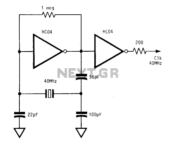
The circuit operates reliably from below 1 MHz to above 400 MHz. With a supply voltage (Vcc) of 5 V, the output of the second inverter achieves a full swing from 0 V to 5 V. These significant logic...

This oscillator may contain several switched crystals to provide channelized operation. A buffer amplifier may be added if desired. The oscillator described is designed to utilize multiple switched crystals, enabling it to operate across various frequency channels. This feature is...
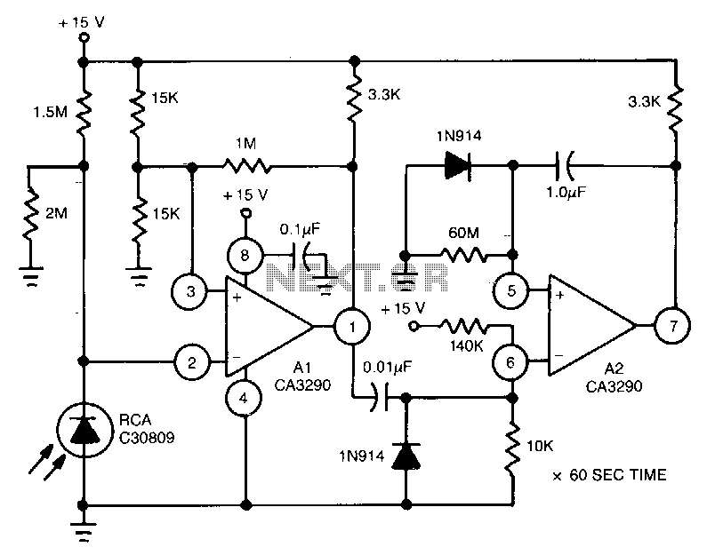
This circuit utilizes the CA3290 BiMOS dual voltage comparator to detect variations in the current of a light-emitting diode (LED). The output from the comparator triggers A2, a one-shot timer. If the light source to the photodiode is disrupted,...
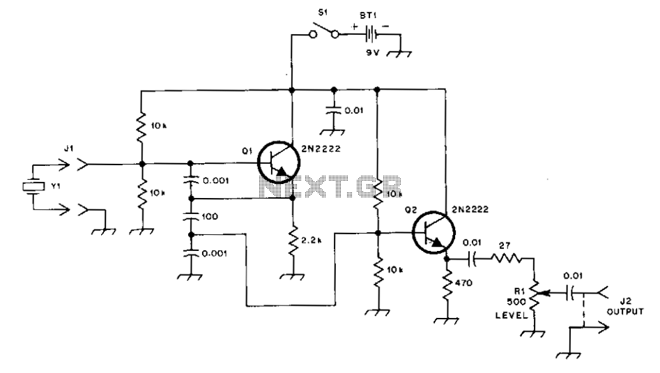
This general-purpose signal source is highly effective for signal-tracing applications. The output level is adjustable, exceeding 1 Vrms into a 50 Ω load. It is compatible with nearly any crystal in the 1 to 15 MHz frequency range. Q1...

The B8422 Nixie tubes are intended for use in an alarm clock on a bedside table. The collection of homemade clocks in the house has expanded, with the bedroom remaining unaffected by this clock-making enthusiasm. The B8422 Nixie tubes,...