
Temperature Controlled Relays 4001/4011
The circuit described consists of two separate temperature control systems that utilize a relay for switching based on temperature thresholds. Each circuit is designed to monitor temperature variations and activate a relay accordingly, either to turn on or off a connected load based on the temperature readings.
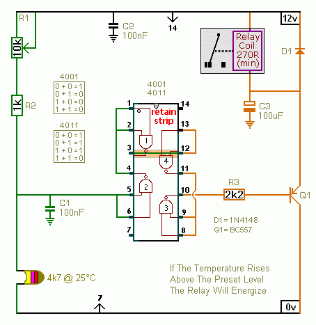
In the first circuit, the relay is activated when the temperature exceeds a predefined upper limit. This is achieved through a thermistor, which changes its resistance with temperature variations. The output voltage at pins 5 and 6 of the circuit is critical for determining the activation of the transistor, which in turn controls the relay. The transistor's role is to amplify the signal from the thermistor, allowing the relay to be energized when the temperature surpasses the set point.
Conversely, the second circuit is designed to energize the relay when the temperature drops below a specified lower limit. This circuit is nearly identical to the first, with the primary distinction being the reversed polarity of the transistor. This configuration ensures that the relay is activated when the temperature falls below the desired threshold.
The thermistor's resistance value is not critical to the overall function of the circuit; however, the voltage across pins 5 and 6 must be monitored to ensure proper operation. Adjustments may be necessary for resistor R1 to calibrate the temperature range for activation, allowing for customization based on specific application requirements.
It is imperative to note that the on-board relay should not be utilized for switching mains voltage due to inadequate isolation between the relay contacts and the low-voltage components. For applications requiring the switching of mains voltage, it is recommended to use a suitably rated relay installed in a safe, isolated location to prevent any potential hazards. This precaution ensures the safety of both the circuit and the user, minimizing the risk of electrical shock or damage to components.The first circuit energizes the relay when the temperature rises above the preset level. The second circuit energizes the relay when the temperature falls below the preset level. The two circuits are practically identical. The only difference between them is the polarity of the transistor. The value of the thermistor is not critical. The important thing is the voltage on pins 5 & 6. Any value thermistor should work satisfactorily. But you may need to change the value of R1 - to achieve the desired range of adjustment. Do not use the "on-board" relay to switch mains voltage. The board's layout does not offer sufficient isolation between the relay contacts and the low-voltage components. If you want to switch mains voltage - mount a suitably rated relay somewhere safe - 🔗 External reference
Related Circuits

The RF engineer occasionally needs to find an instrument that can reliably and quickly test a low-frequency quartz crystal unit. This equipment is often challenging to locate, leading engineers to consult electronic circuits handbooks for schematics that can perform...

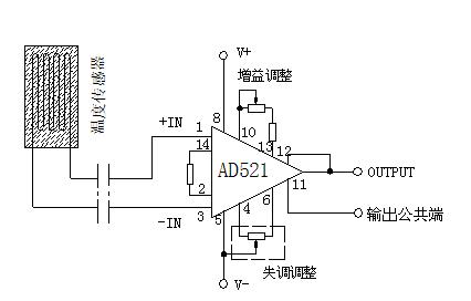
When the RTD temperature sensor is positioned far from the amplifier, the resistance of the sensor leads and their susceptibility to interference and other issues cannot be overlooked. The circuit shown in the figure addresses this problem. It utilizes...

This circuit is a precision amplifier with digital control, designed for signal conditioning of low-output transducers operating in the millivolt range. The resistors R3 to R6 can be user-selected, with values ranging from 1 kilo-ohm to 1 mega-ohm, allowing...

An embedded C-based RF-controlled robot equipped with a metal detector, along with wireless image and voice transmission capabilities. This project report is intended for electronics and communication engineering students. The project involves the design and implementation of an RF-controlled robot...
The component is deformed due to various thermal influences during processing, which compromises the original machining accuracy and introduces errors. In precision finishing, the effect of thermal deformation is particularly significant, leading to processing errors that can exceed 40%....

A radio-controlled electronic flash is a valuable tool in any photographer's kit, frequently utilized by professionals. For instance, a wedding photographer may position one behind the bride to illuminate her gown and veil, avoiding visible wires in the shot....