
Motor time division control circuit composed of transistor and NE555

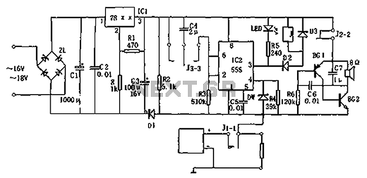
The circuit depicted in Figure 2-32 (a) represents a control system for an electric motor that can alternate between running and generating modes. The operation is initiated by the user through switch S1, which has two positions: position 1 for motor operation and position 2 for generator operation.
In position 1, the power driver circuit is engaged, allowing current to flow to the motor. This current is responsible for the motor's operation, converting electrical energy into mechanical energy to perform work. The driver circuit typically consists of a transistor or a relay that acts as a switch, controlling the flow of current based on the switch's position.
When S1 is switched to position 2, the power to the motor is cut off, halting its operation. In this mode, the motor begins to act as a generator due to its inertia. The mechanical energy stored in the motor is converted back into electrical energy, generating a back electromotive force (EMF). This generated voltage can be utilized in various applications, such as charging batteries or supplying power to other circuits.
The sampling circuit plays a crucial role in this configuration. It monitors the back EMF produced by the motor during the generator mode. This feedback is essential for ensuring that the system operates efficiently and safely, as it can prevent over-voltage conditions that may damage the components. The sampling circuit typically includes resistors, capacitors, and possibly an operational amplifier to condition the signal for further processing.
Overall, this schematic showcases a versatile motor control system that can efficiently switch between driving and generating modes, utilizing a simple switch to manage the operational state of the motor while incorporating safety features through the sampling circuit. The design is applicable in various fields, including renewable energy systems, electric vehicles, and automated machinery.Figure 2-32 (a) shows the time control diagram, and the motor is operated by the switch S1. When Sl is turned to 1, the power driver circuit provides current to the motor for running; When S1 is turned to 2, the drive current is cut off, and the electric motor is used as a generator to hold out the back electromotive force by the sampling circuit. S1is turne.. 🔗 External reference
Related Circuits
The circuit presented is designed to prevent burning one's tongue by monitoring the temperature of coffee. It consists of a voltage regulator, a temperature-to-voltage converter, a comparator, and two LEDs. In general, the circuit operates as follows: if the...
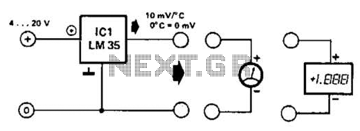
An effective temperature sensor circuit is designed to receive power from a 4-to-20 mA loop without impacting the loop current. The temperature sensor integrated circuit (IC) used is the AD590F, which operates with a supply voltage ranging from 4...
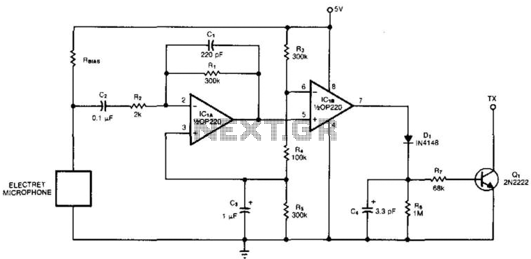
An electret microphone feeds a bandpass filter circuit (IC1A), which subsequently drives a comparator. This comparator activates Q1, a switch that conducts when audio signals from IC1B cause D1, C4, R6, and R7 to bias it ON. The circuit begins...
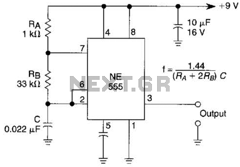
An astable multivibrator based on the 555 timer is presented. The frequency is approximately 975 Hz, determined by the values of RB and C. The astable multivibrator configuration using the 555 timer is a popular circuit for generating square wave...
Circuit diagram for a DC power supply protection circuit. The device includes a buck rectifier power supply, a monostable delay circuit, a relay control circuit, and an audio feedback oscillation circuit. The entire circuit operates with a DC voltage...
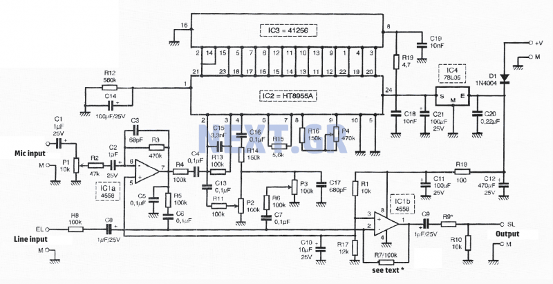
This fast circuit is compatible with any amplifier that has a line or high-level input (radio, CD) that allows mixing signals from a microphone with a chosen music source and adding adjustable sound effects to the voice. The circuit...