
Motorcycle anti-thief alarm circuit (11)
The motorcycle anti-theft alarm circuit is designed to provide security for motorcycles by detecting unauthorized movement and activating an alarm. The detection alarm circuit plays a crucial role in this system. It utilizes a mercury switch (S1) that closes its contacts when the motorcycle is tilted or moved, indicating potential theft. This switch is connected to a series of resistors (R1-R3) that help to set the sensitivity of the circuit and ensure proper functioning.
The capacitor (C) serves to filter and stabilize the voltage supply to the transistors (V1 and V2). These transistors act as amplifiers, boosting the signal from the mercury switch to trigger the alarm. The alarm itself is a high-decibel sound generator that alerts the owner and deters potential thieves.
The charging circuit is essential for maintaining the power supply to the alarm system, ensuring it remains operational even when the motorcycle is parked for extended periods. This circuit typically includes a rechargeable battery that is charged while the motorcycle is running, providing a reliable power source for the alarm system.
The anti-theft control circuit integrates the detection alarm and charging circuits, allowing for seamless operation. It may also include additional features such as remote control activation, LED indicators for status, and a delay timer to prevent false alarms during normal use.
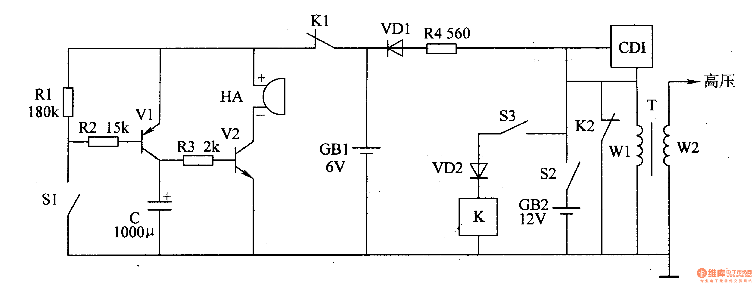
Overall, the motorcycle anti-theft alarm circuit is a sophisticated system that combines various electronic components to enhance the security of motorcycles, providing peace of mind to owners.The principle of the circuit The motorcycle anti-thief alarm circuit is composed of the detection alarm circuit, the charging circuit and the anti-theft control circuit, this circuit is as shown in figure 7-94. The detection alarm circuit is composed of the mercury switch Sl, the resistors Rl-R3, the capacitor C, the transistors V1, V2 and the high loudnes..
🔗 External reference
Related Circuits
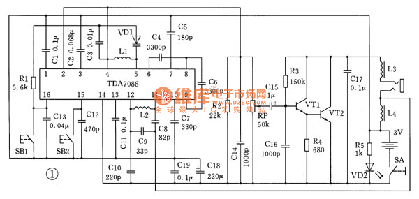
This is the schematic diagram for an automatic search FM radio. The primary component is the TDA7088 integrated circuit, which encompasses the FM radio receiver, antenna, oscillator, mixer, automatic frequency control (AFC) circuit, intermediate frequency amplifier (with an IF...
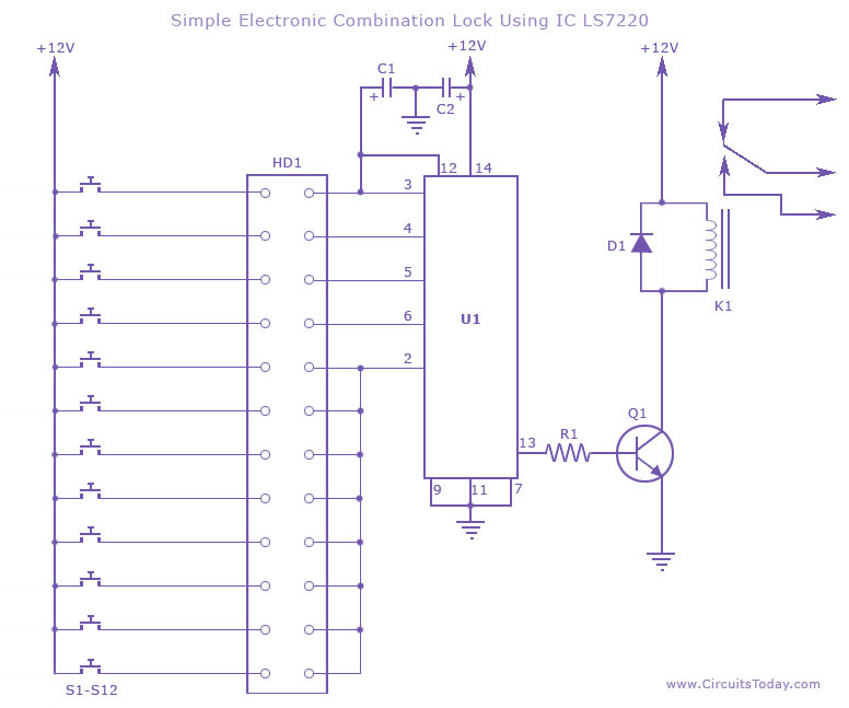
This circuit diagram illustrates a simple electronic combination lock utilizing the IC LS7220. It is designed to activate a relay for controlling any device (on & off) when a specific combination of four digits is entered. The circuit operates...
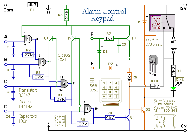
Pressing a single key on the keypad energizes the relay. Entering a four-digit code of your choice de-energizes the relay. This circuit is designed to control a Modular Burglar Alarm System but can be applied in other scenarios. A...
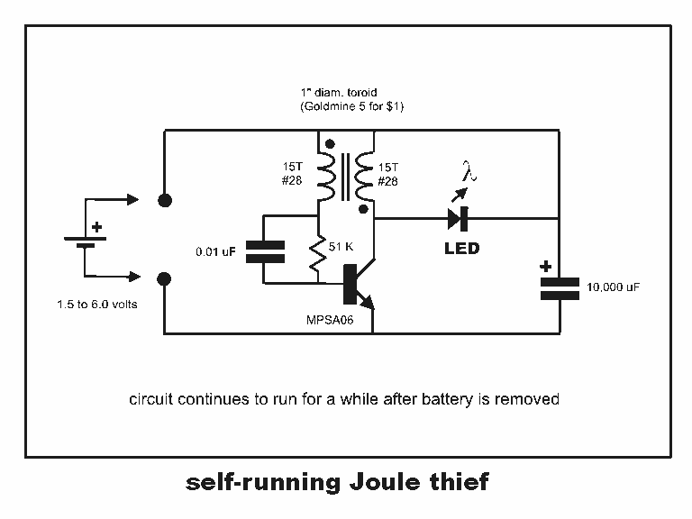
Professor Steven E. Jones' circuit demonstrates an 8x overunity. The concept of overunity refers to a system that produces more energy than is consumed, effectively achieving a coefficient of performance greater than one. In the context of Professor Steven E....
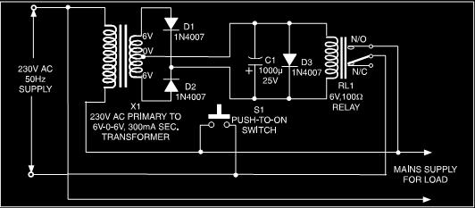
This is a low-cost protection circuit designed to safeguard electrically operated home appliances, such as TVs, DVD players, refrigerators, and other devices, during sudden power outages and the subsequent restoration of mains supply. Appliances like refrigerators and air conditioners...
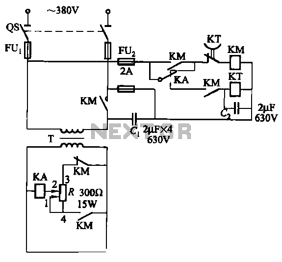
The relays in the AC arc welding machine manage the load through a three-way power circuit, as depicted in Figure 522. The selected relay type is KA, operating at 24V. Additionally, the time relay KT is of the JS7...
Warning: include(partials/cookie-banner.php): Failed to open stream: Permission denied in /var/www/html/nextgr/view-circuit.php on line 713
Warning: include(): Failed opening 'partials/cookie-banner.php' for inclusion (include_path='.:/usr/share/php') in /var/www/html/nextgr/view-circuit.php on line 713