
Three Relays AC arc welding machine circuit
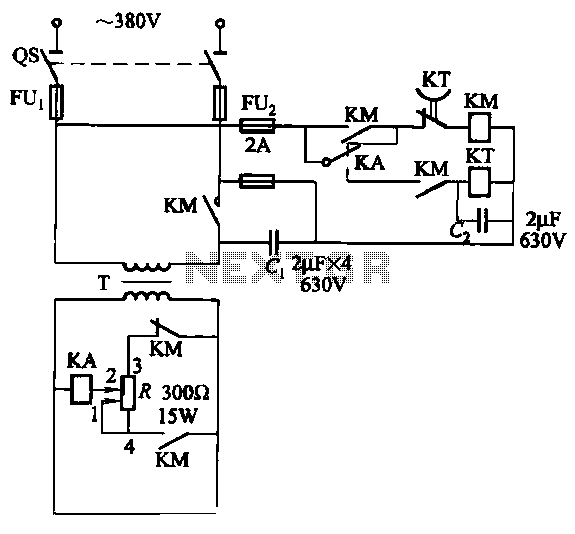
The AC arc welding machine utilizes a three-way power circuit to efficiently control the welding process. The relay KA, rated at 24V, serves as a critical component in managing the load. This relay is responsible for switching the power on and off, ensuring that the welding operation is conducted safely and effectively. Its selection is crucial as it must handle the operational parameters of the welding machine, including voltage and current ratings.
The time relay KT, specifically the JS7 model, incorporates a timing mechanism that allows for precise control over the duration of the welding operation. With a timing range from 0.4 to 180 seconds, this relay can be configured to suit various welding applications, enabling adjustments based on the material being welded and the desired weld characteristics. The ability to set the time delay is essential for achieving optimal weld quality and ensuring that the welding process is completed efficiently.
In the schematic representation, the connections between the relays and the power circuit are illustrated, highlighting the flow of current and the operational sequence. The relay KA is typically connected to the primary power supply, while the time relay KT interfaces with the control circuit to initiate and terminate the welding cycle based on the preset timing parameters. Proper integration of these components is vital for the reliable operation of the AC arc welding machine, contributing to its overall performance and safety.Relays AC arc welding machine load since the three-way power circuit shown in Figure 522 relay KA selection type, 24V; time relay KT selection JS7 Ying, 0.4-180s.
Related Circuits
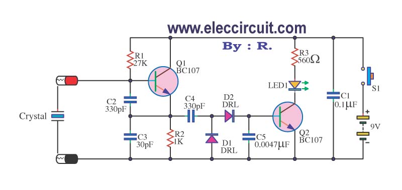
A multimeter cannot be used to test a crystal oscillator. Instead, a dedicated circuit is required, capable of checking crystals within the frequency range of 100 kHz to 900 MHz. This circuit is easy to construct and cost-effective. To construct...
The image depicts a proximity switch circuit that includes the HMC1001 Hall effect sensor, an operational amplifier (AMP04), and a light-emitting diode (LED). In this configuration, the operational amplifier functions as a comparator. When a magnet with a length...

The circuit utilizes a dual operational amplifier integrated circuit (IC), specifically the 1458, which contains two separate op-amps within a single package. In this configuration, the first op-amp functions as a voltage follower, directing its output to charge capacitor...
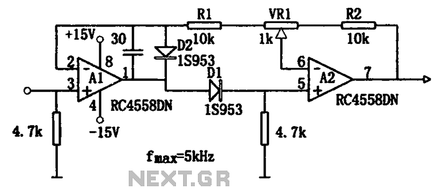
The circuit illustrates a simple method for adjusting the high input impedance of a double wave linear detector. It employs an operational amplifier configured with a negative feedback loop to compensate for the non-linear behavior of the diode used...

This digital dice circuit is designed to display numbers effectively. When the spin switch is turned off, it converts the input into a binary format using a diode matrix composed of diodes D1 to D9 (1N4148 or 1N914). This...
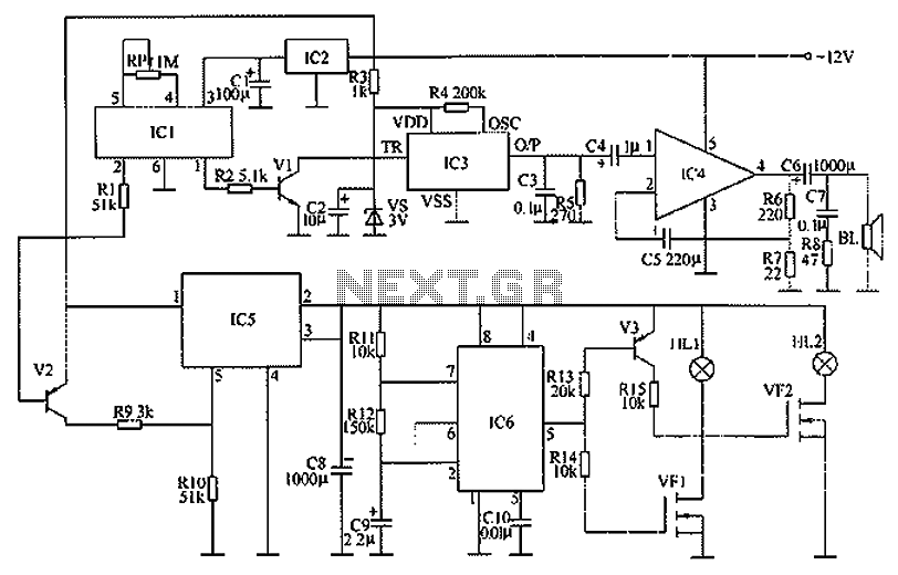
The circuit functions as a danger zone warning system incorporating a regulator circuit, a pyroelectric infrared detection trigger circuit, an electronic switching circuit, and audio circuits. The regulator circuit includes a three-terminal regulator integrated circuit (IC2), a resistor (R3),...