
Multi function frequency meter 0-100MHz using ICM7226B

The multifunction frequency meter is designed to provide accurate measurements of frequency, voltage, current, and other electrical parameters in a compact format. This device typically features an 8-digit 7-segment LED display, which allows for clear visibility of the readings. The meter is equipped with multiple input channels, enabling it to switch between different measurement types seamlessly.
The core of the multifunction frequency meter consists of a microcontroller or a digital signal processor (DSP) that processes the incoming signals. The microcontroller interprets the data from the sensors and converts it into a readable format for the display. The input stage may include signal conditioning components such as amplifiers and filters to ensure that the measurements are accurate and free from noise.
Control buttons are integrated into the design, allowing users to select the desired measurement mode, adjust settings, and calibrate the device as needed. The user interface is designed to be intuitive, with clear labeling on the controls corresponding to different functions.
Power supply requirements for the meter can vary, but it typically operates on a low-voltage DC source, ensuring safety and portability. Additionally, the device may include features such as data logging capabilities, allowing users to record measurements over time for analysis.
In summary, the multifunction frequency meter is a versatile tool suitable for various applications in electronics, maintenance, and laboratory settings, providing users with essential measurement capabilities in a single, user-friendly instrument.The Multi function frequency meter is an instrument that can measurement many things in a single display with LED 7 segment 8 digit. The controls measures.. 🔗 External reference
Related Circuits
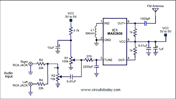
A simple single-chip FM transmitter circuit with a diagram and schematic using the IC MAX 2606, which is a high-performance voltage-controlled oscillator (VCO). The FM transmitter circuit utilizing the MAX 2606 is designed for efficient frequency modulation of audio signals....
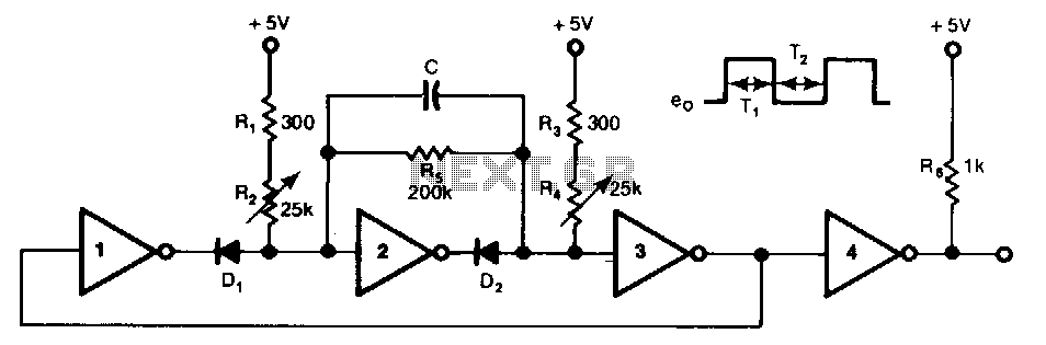
This free-running TTL square-wave oscillator features a variable frequency output spanning a 20:1 range or better. It utilizes four of the six inverters in an SN7404 chip along with additional components. The frequency of oscillation is dictated by the...
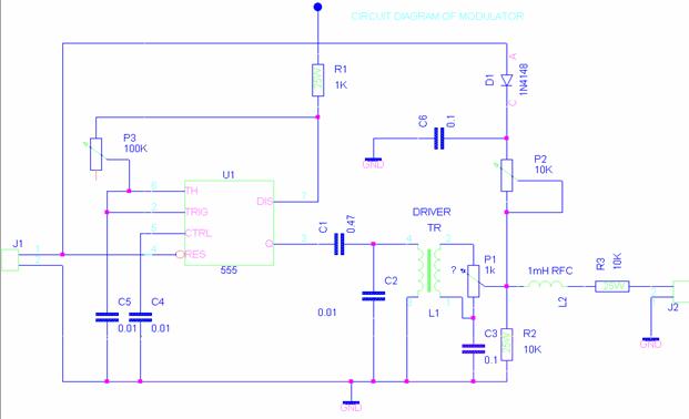
The beacon controller is designed to telemeter data from the VUSAT in Morse code, allowing ham radio operators to decode the information without requiring expensive or complex equipment. The design adheres to the KISS (Keep It Simple, Stupid) principle,...
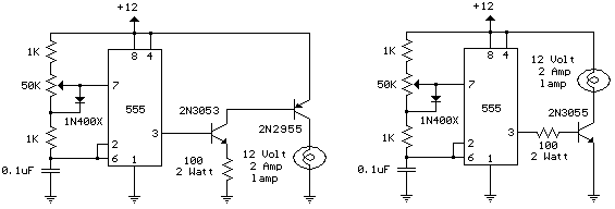
The schematic diagram illustrates a 12 Volt Car Lamp Dimmer Circuit Design utilizing a 555 Timer. This circuit can be employed to dim a standard 25-watt lamp. The 12 Volt Car Lamp Dimmer Circuit utilizes a 555 Timer in astable...
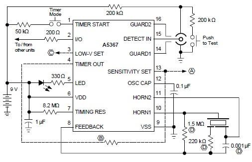
A simple ionization smoke detector with interconnect and timer alarm circuit can be constructed using the A5367 low-current, CMOS circuit, which provides all essential features for an ionization-type smoke detector. This CMOS IC, manufactured by Allegro MicroSystems, includes interconnect...
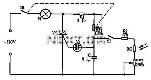
Circle S2 is a stable automatic light switch. When S2 is open, the entire circuit operates as a subsection II SCR stepless presentation dimmer, omitting the high-frequency filter circuit. The trigger diode switch activates a neon indicator bulb (V),...
Warning: include(partials/cookie-banner.php): Failed to open stream: Permission denied in /var/www/html/nextgr/view-circuit.php on line 713
Warning: include(): Failed opening 'partials/cookie-banner.php' for inclusion (include_path='.:/usr/share/php') in /var/www/html/nextgr/view-circuit.php on line 713