
Multi Rocket Launcher

The launch controller described operates as a simple electrical circuit designed for igniting low voltage battery igniters in model rocketry applications. The circuit primarily consists of a power source, a push button switch, and an output connection to the igniter. The use of "C" cell batteries is notable as they provide a higher current capacity compared to "AA" batteries, making them suitable for applications requiring more power, such as igniting rocket engines.
The push button switch is a crucial component, designed to handle a current rating of 1 amp or higher, ensuring reliable operation during the ignition process. When the button is pressed, it completes the circuit, allowing current to flow from the battery through the switch to the igniter. This momentary connection is sufficient to heat the igniter element, initiating combustion in the rocket engine.
The output connection to the igniter is facilitated through a 3.5-inch jack plug, which allows for easy and secure attachment of the igniter wire. This design choice not only isolates the igniter from the controller when not in use, enhancing safety, but also provides a standardized connection method that can be easily adapted for different igniter types.
The circuit for a single rocket is straightforward, consisting of the battery connected in series with the push button switch and the igniter. This simplicity ensures ease of assembly and troubleshooting, making it accessible for hobbyists and educators alike. Overall, the launch controller exemplifies effective design principles for safe and reliable model rocketry applications.This launch controller can be used with low voltage battery igniters, which fire rocket engines in model rockets such as the Estes range. These circuits are electrical, only switches and contacts are involved. First the circuit for a single rocket. A point to note here is that this controller uses "C" cells, providing more current than "AA" batteries and that the push button switch has contacts rated 1 amp or higher. The wire to the igniter is isolated via a 3.5 inch jack plug an 🔗 External reference
Related Circuits
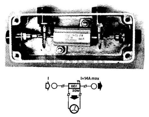
The current range in multimeters, especially the more affordable models, is limited by the load capacity of the internal shunts to 1 to 2 A. A precision heavy-duty resistor from manufacturers such as Dale or RCL (0.1 Ω; 20...
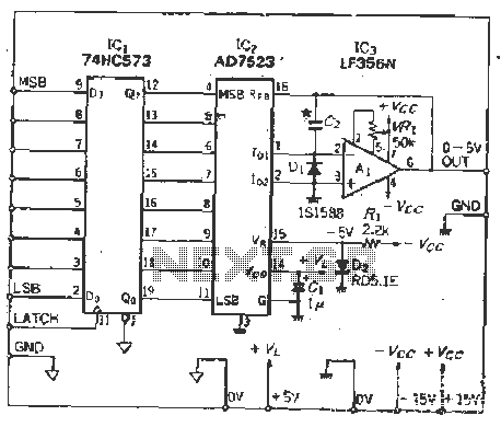
The IC latch is utilized to hold the digital data when the clock signal rises. The configuration includes a holding data port AD7s23, a thin film resistor ladder, and a switch that together form an 8-bit Digital-to-Analog Converter (DAC)....
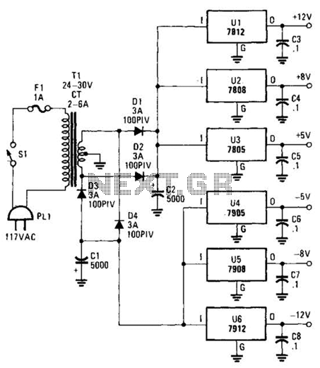
This dual-polarity, multivoltage power supply can be constructed with a minimal investment. The circuit utilizes 78XX and 79XX series voltage regulators, four 3-A diodes, a 24-30 V, 2-6 A transformer, and eight filter capacitors. The described dual-polarity, multivoltage power supply...

A multivibrator is an electronic circuit that implements various simple two-state systems, such as oscillators, timers, and flip-flops. The most common type is the astable multivibrator, which continuously oscillates between two states, generating a square wave. Another type is...
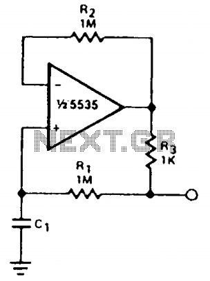
The circuit can be utilized to simulate large capacitances using components of smaller values. With the specified values and a capacitance of 10 µF, an effective capacitance of 10,000 µF was achieved. The quality factor (Q) is constrained by...
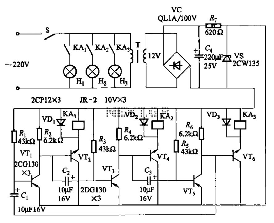
The transistors VTi, VT3, and VTs, along with the RC components, form three distinct multi-resonator oscillators. The oscillation frequency levels are dependent on the values of Ri, R3, Rs, and Cl, as well as Cz and C3s. The circuit comprises...