
Capacitance multiplier

The described circuit functions by employing a technique known as capacitance multiplication, which allows for the simulation of high capacitance values using lower-rated capacitors and resistors. This principle is particularly advantageous in applications where space and component size are critical.
In this configuration, a small capacitor (C) of 10 µF is used in conjunction with a resistor (R1) to create a network that effectively multiplies the capacitance. The effective capacitance (C_eff) achieved can be significantly higher than the actual capacitance of the capacitor used. The multiplication factor is determined by the values of the resistors and capacitors in the circuit, as well as the frequency of operation.
The effective series resistance (ESR) plays a crucial role in determining the quality factor (Q) of the circuit. A lower ESR results in a higher Q, which is desirable for applications requiring minimal energy loss and improved performance. Consequently, R1 should be chosen to be as large as feasible without compromising the circuit's operational stability or responsiveness.
In practical implementation, careful consideration must be given to the selection of components to ensure that they can handle the voltage and current requirements of the application. The circuit can be employed in various scenarios, including power supply filtering, energy storage systems, and timing applications where large capacitance values are required but larger physical components are not feasible.
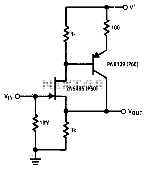
Overall, this circuit design demonstrates an effective method for achieving high capacitance values through strategic component selection and configuration, enhancing both performance and versatility in electronic applications.The circuit can be used to simulate large capacitances using small value components. With the values shown and C - 10 µ¥, an effective capacitance of 10,000 µF was obtained. The Q available is limited by the effective series resistance. So R1 should be as large as practical.
Related Circuits
The 2N5485 features low input capacitance, making this compound series-feedback buffer a wide-band unity gain amplifier. The 2N5485 is a field-effect transistor (FET) that is often utilized in applications requiring low noise and high input impedance. Its low input capacitance...
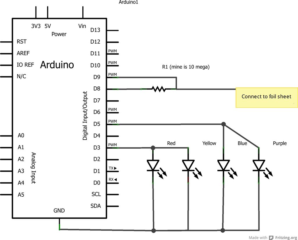
This project is an Arduino-based light control system that is ideal for beginners. It allows the fading of colors or lights by detecting hand movements nearby. The system transitions from a purple-blue hue to a fiery red-orange. The assembly...
Because it uses few parts, a printed circuit board is not necessary; components can simply be soldered to one another. However, a box is desirable for operating convenience. The case and aerial from a discarded toy walkie-talkie was used...
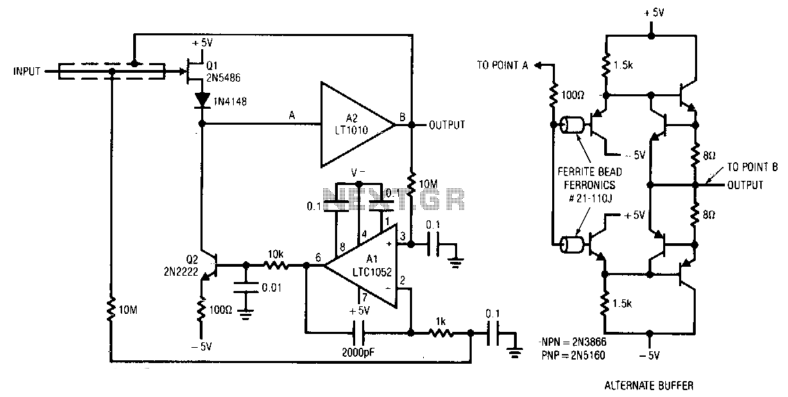
Q1 and Q2 form a simple, high-speed FET input buffer. Q1 operates as a source follower, while Q2 serves as a current source load that sets the drain-source channel current. The LT1010 buffer provides the necessary output drive capability...
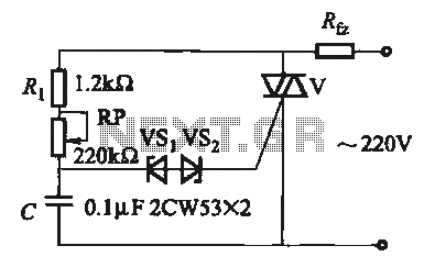
The introduction for a unidirectional thyristor trigger circuit is also applicable to the TRIAC. Several bidirectional circuits are illustrated in Figure 16-28. Figures 16-28 (a) and (b) depict a direct trigger circuit; Figure 16-28 (c) illustrates a dual diode...
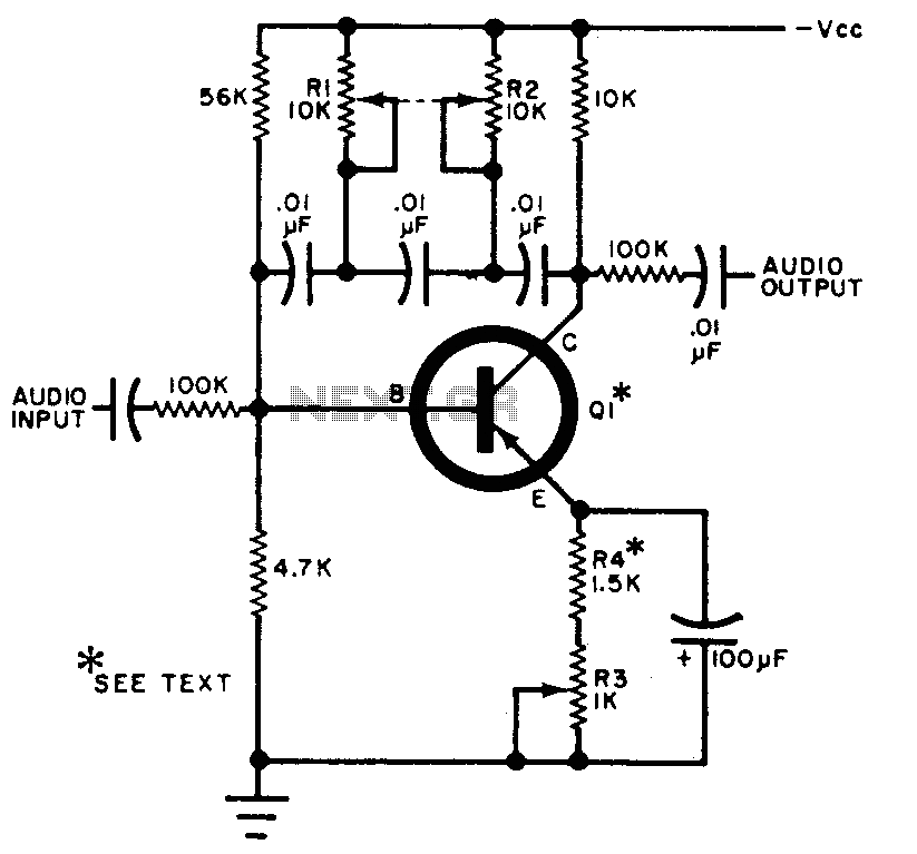
The circuit can be selectively tuned to two closely related tones. The selective frequency is determined by the values of the feedback circuit connected to the collector and base of Q1, which includes capacitors and resistors. When the specified...