
Multifunctional Battery Protector

The circuit operates as a battery protector by monitoring the voltage levels during the charging process. When the voltage exceeds a predefined threshold, the circuit automatically disconnects the battery from the charging source to prevent damage from over-voltage conditions. The design is energy-efficient, consuming less than 20mA of current, which is critical for applications where power conservation is essential.
The circuit utilizes components such as the MAX8212, which serves as a voltage supervisor, ensuring that the battery is charged within safe limits. The PCB layout is designed for ease of assembly, with clearly marked connections for the battery, charging input, and output to the load. The schematic diagram provides a visual representation of the circuit, detailing the interconnections between components and their respective values.
The images provided in the post include various layouts and diagrams, offering a comprehensive guide for enthusiasts looking to assemble the battery protector circuit. Each image highlights different aspects of the design, from the overall PCB layout to specific component placements, ensuring clarity in the assembly process.
Additionally, the tags associated with the post facilitate navigation to similar projects and resources, enhancing the learning experience for users interested in battery management systems. Overall, this multifunctional battery protector circuit represents a practical solution for safeguarding batteries against over-voltage, making it a valuable addition to any battery-operated device.The circuit can cut-outs the over-load voltage of battery while charging. Work automatically charge and recharge, very-low power load less than 20mA, suitable for use with 4. 8-12. 5V batteries. At this post, we, Tasel team uploaded several image which can be your master for this project. You can download them then print them out to make your real b attery protector by your own hand. its pleasure for us if you also give your little time to comment and give a rating for this post. This PCB Back Parts Multifunctional Battery Protector Circuit post content written by TB in May 18th, 2012. Contain total 6 images, such as multifunctional battery protector back layouts parts, multifunctional battery protector layout parts and pcb, multifunctional battery protector circuit diagram in group among pcb back parts multifunctional battery protector circuit, pcb layout multifunctional battery protector circuit, pcb front parts multifunctional battery protector circuit in group among fell free to browse each image from this post content.
This post content actually have 13 labels, such as MAX8212, Battery Protector Diagram, Battery Saver Circuit in group among Battery Protector, Battery Charger, Battery Protector Circuit as well as Multifunctional Battery Protector PCB, Battery Guardian, Automatic Charger Circuit and Automatic Charger, Battery Saver Diagram, other tags from other post content, we collect and place them in a tag cloud which located above of footer. With those tags, you will see other related post content which have a similar term on it. 🔗 External reference
Related Circuits
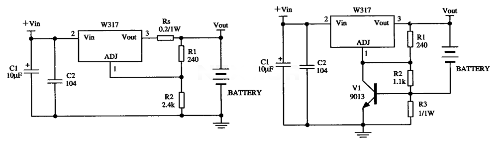
The W317 circuit integrates a three-terminal adjustable voltage regulator designed for battery charging applications. It features a constant pressure limiting charger circuit, where resistor Rs is employed to restrict the charge current, thereby reducing the initial charge rate. Additionally,...
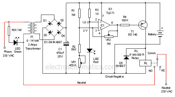
This is a 12-volt lead-acid automatic battery charger that stops the charging process once the battery reaches a full charge. This feature prevents overcharging. The 12-volt lead-acid automatic battery charger is designed to efficiently charge lead-acid batteries while ensuring safety...

This circuit delivers an initial voltage of 2.5V per cell to rapidly charge a car battery. The charging current decreases as the battery charges. This circuit is designed to provide an efficient charging solution for car batteries by applying an...
While traveling, charging a mobile phone can be a significant challenge due to the general inaccessibility of power supply sources, leading to the risk of the battery depleting. To address the issue of mobile phone battery depletion during travel, a...
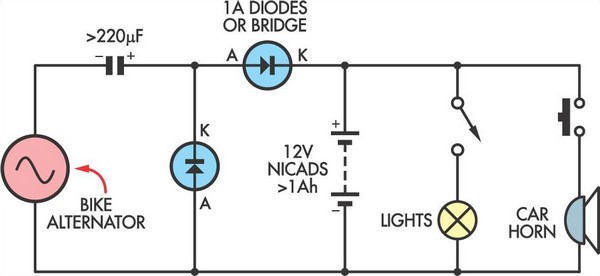
This simple circuit enables a 12V battery pack to be charged using a bike generator. The generator is rated at 3W and, with the inclusion of a voltage multiplier circuit, delivers approximately 200mA at a speed of around 15...

12V NiCad battery charger with a 200mA/h power supply. Refer to the specified page for an explanation regarding the related circuit diagram. The circuit for a 12V NiCad battery charger designed to supply a current of 200mA/h typically includes several...