
Battery consists Wll7 W217 W317 configuration application circuit
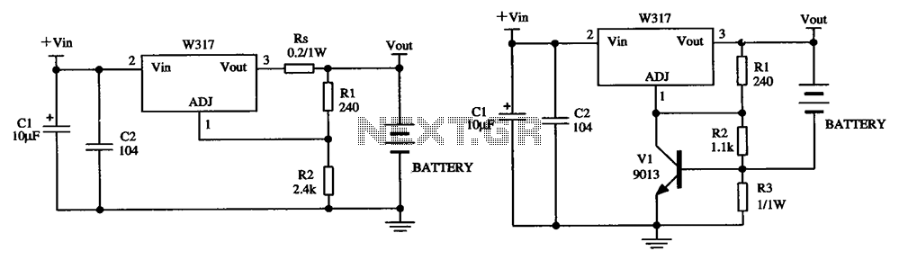
The W317 adjustable voltage regulator circuit serves as a versatile solution for battery charging applications, enabling precise control over the voltage and current supplied to the battery. The circuit is designed to ensure safe charging conditions by incorporating various current-limiting components that help prevent damage to both the battery and the charging circuitry.
In the first configuration, the constant pressure limiting charger circuit utilizes resistor Rs to manage the initial charge rate. This is crucial in preventing excessive current from flowing into the battery when it is in a low state of charge, which could otherwise lead to overheating or damage. The value of Rs should be selected based on the specifications of the battery being charged, taking into account its capacity and recommended charge current.
The second configuration introduces an additional layer of protection through the use of resistor R3. This resistor is strategically placed to limit the maximum charging current that can pass through the transistor, thereby protecting it from potential overload conditions. By carefully calculating the resistance value of R3, the maximum allowable current can be set, ensuring that the transistor operates within its safe limits throughout the charging process.
Overall, the W317 adjustable voltage regulator circuit exemplifies a well-thought-out design that not only provides adjustable voltage output but also incorporates essential safety features to enhance the reliability and efficiency of battery charging operations. Proper implementation of these components will result in a robust charging solution suitable for a variety of battery types. As shown by W317 is being integrated three-terminal adjustable voltage regulator circuit consisting of a battery charging applications. FIG. (A) given constant pressure limitin g charger circuit, wherein Rs is used to limit the charge current, to reduce the initial charge rate; Figure (b) is given still another limiting charging circuit, and wherein the resistor R3 used to limit the maximum charging current of the transistor.
Related Circuits
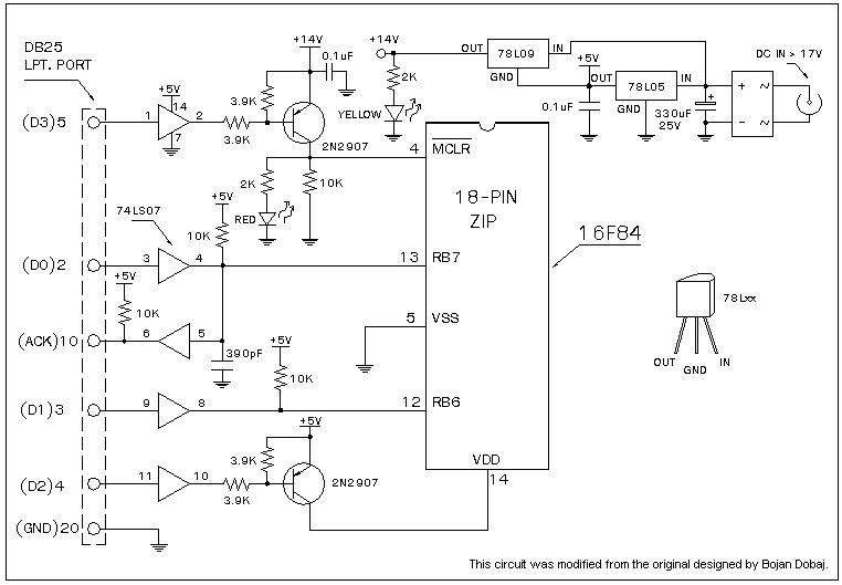
A universal Windows-based software designed to work with any serial programmers for the PIC16F84, known as WPicProg16 V1.20. It is recommended to build this programmer before starting various interesting projects with the F84. Some PIC programmers support in-circuit programming,...
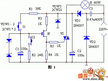
The keyer dimmer table lamp utilizes two touch buttons to adjust the light intensity. When one button is touched, the light dims from a strong brightness, while the other button increases the brightness from a dim state. The working...

This is a design circuit for a UHF transmitter. The TV transmitter operates within the UHF frequency range of 470-580 MHz, specifically on channels 21-34. It can transmit signals over distances of 30-100 meters using a cable length of...
Any NPN transistor can be used. The author used a 2N3904, but a 2N2222A should work just as well. A good, low noise transistor would be even better. Some radios only have three connections to their ferrite bar antenna:...
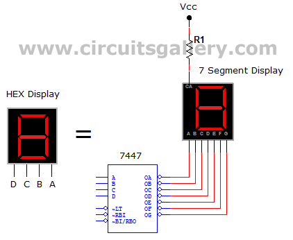
This circuit defines seven levels in a reservoir. The sensed values are connected to an encoder circuit, which consists of a 74148 integrated circuit (IC), functioning as an 8-line to 3-line encoder. The next section features a HEX display,...
This project is used as an electronic private exchange. It has two telephones, which have the intercom facility, and they can be connected to the telephone line. All the functions are controlled by the 8-bit microcontroller AT89C2051 which has...