
12 v nicad battery charger 200mah

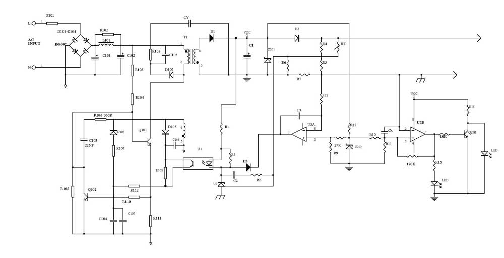
The circuit for a 12V NiCad battery charger designed to supply a current of 200mA/h typically includes several key components to ensure safe and efficient charging. The main components include a transformer, a rectifier, a voltage regulator, and a current limiting resistor.
1. **Transformer**: The transformer steps down the AC mains voltage to a lower AC voltage suitable for charging a 12V battery. A transformer with a secondary voltage rating of approximately 12V-15V is commonly used to account for voltage drops in the subsequent components.
2. **Rectifier**: Following the transformer, a bridge rectifier is employed to convert the AC voltage into DC voltage. The bridge rectifier consists of four diodes arranged in a bridge configuration, allowing current to flow in one direction and providing a full-wave rectification. This results in a pulsating DC output.
3. **Smoothing Capacitor**: To reduce the ripple voltage from the rectified output, a smoothing capacitor is connected in parallel with the output. This capacitor stores charge and releases it when the voltage dips, providing a more stable DC voltage to the battery.
4. **Voltage Regulator**: A voltage regulator is often included to maintain a consistent output voltage, ensuring that the battery is charged safely without exceeding its voltage rating. A linear voltage regulator, such as the LM7812, can be used to regulate the output to approximately 12V.
5. **Current Limiting Resistor**: To prevent overcharging and to control the charging current, a current limiting resistor is implemented in series with the battery. The resistor value is calculated based on the desired charging current (200mA) and the voltage drop across the resistor.
6. **LED Indicator**: An LED may be included in the circuit to indicate the charging status. This LED can be connected in parallel with the battery or in series with a resistor to limit current, providing visual feedback when the charger is active.
7. **Protection Diodes**: To protect the circuit from reverse polarity and potential damage, protection diodes can be added. These components ensure that if the battery is connected incorrectly, the circuit remains unharmed.
The overall design of the 12V NiCad battery charger should adhere to safety standards, including proper heat dissipation for components that may generate heat during operation. Additionally, it is essential to ensure that the circuit is compact and efficient for practical use in battery charging applications.12V Nicad Battery charger 200mA/H power supply. Go to that page to read the explanation about above power supply related circuit diagram. 🔗 External reference
Related Circuits
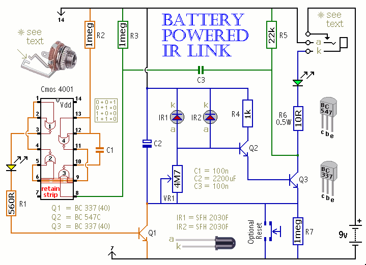
This is a battery-powered infrared (IR) link that can be utilized in multiple rooms. The standby current is exceptionally low, resulting in excellent battery life. The circuit is designed to shut down when faced with extraneous IR radiation, effectively...
Here's how to make a good charger for a sealed lead-acid battery (this will NOT work with NiCad batteries) that’s faster (because it allows more current into the battery initially) and safer (because it uses lower voltage when the...
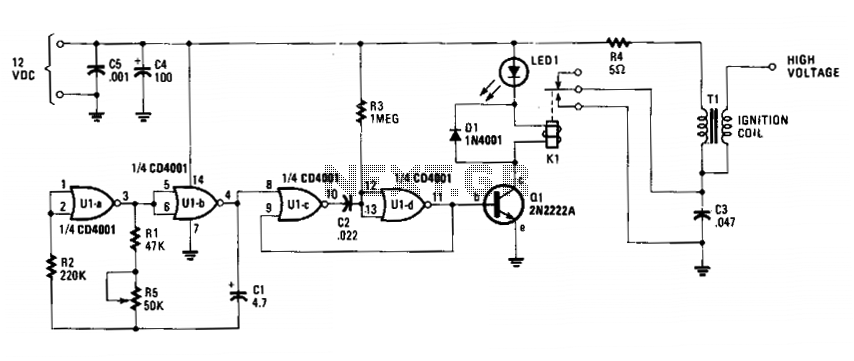
The circuit is fundamentally an auto ignition coil paired with a set of points that perform a similar function. It employs a pulsing circuit constructed from a single CMOS NOR integrated circuit (U1) to open and close relay contacts,...
Powering the system is required by many applications while charging the battery simultaneously. Interaction between the system and charger may result in a... Power management in electronic systems is critical, particularly in applications that necessitate simultaneous operation and battery charging....
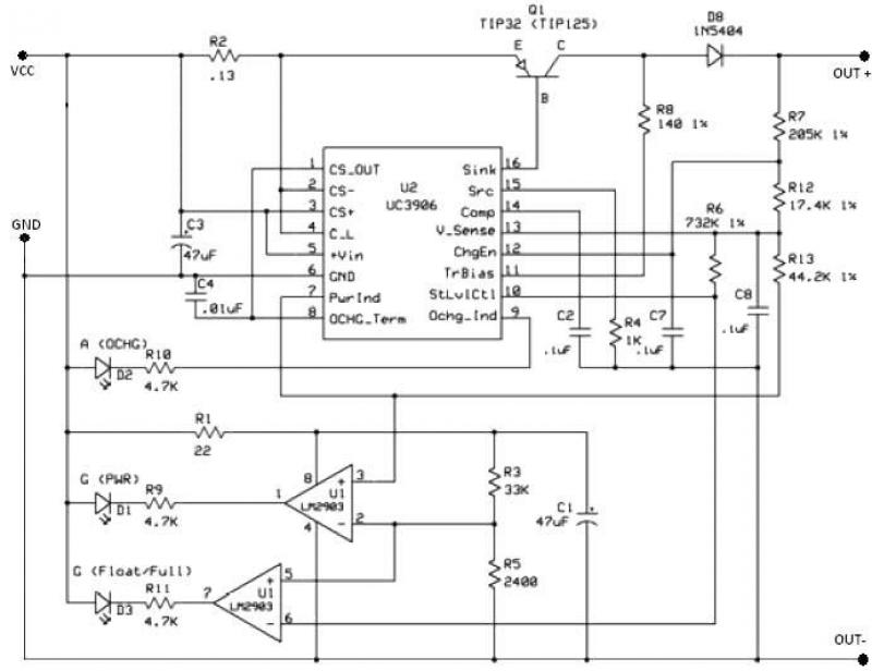
The UC3906 battery charger circuit controller includes all necessary circuitry to manage the charge and hold cycles for sealed lead-acid batteries. This circuit is specifically designed to deliver the appropriate charging voltage and current based on the battery's temperature...
Several schematic drawings of battery charger circuits are provided. These circuits cover 5W to 200W for NiCd, NiMH, Lead-Acid, Li-Ion/Polymer, and LiFePO4 battery packs. The charger circuit files aim to assist users in selecting the appropriate chargers and to...