
Multiple-feedback bandpass filter
Typical audio filters utilize capacitor values ranging from 0.01 µF to 0.1 µF, which leads to reasonable values for the resistors.
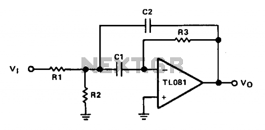
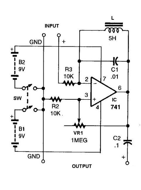
The described circuit employs an operational amplifier in an inverting configuration, which is a common topology for implementing active filters. In this arrangement, the gain is primarily determined by the feedback resistor R3 and the input resistors R1 and R2. The relationship between these resistors directly influences the frequency response of the circuit.
The frequency-determining capacitor C1 plays a crucial role in setting the cutoff frequency of the filter. The feedback capacitor C2, which is equal in value to C1, ensures that the phase shift and frequency response remain consistent. This equality is vital for maintaining the desired filter characteristics.
The adjustable resistor R2 allows for fine-tuning of the center frequency, enabling the designer to optimize the filter for specific audio applications. The formula provided for the center frequency, f0, indicates that it is inversely proportional to the product of the resistors and the capacitance. Therefore, careful selection of R1, R2, and C1/C2 values is essential for achieving the desired filtering effect.
In practical applications, the capacitor values typically range from 0.01 µF to 0.1 µF. This range is standard for audio filters, as it provides a good balance between frequency response and component size. The chosen capacitor values will dictate the values of the resistors R1 and R2, ensuring that the filter operates effectively within the desired frequency range.
Overall, this op amp-based filter circuit provides a versatile solution for audio signal processing, with the ability to adjust the center frequency and maintain consistent performance through the careful selection of component values.The op amp is connected in the inverting mode. Resistor R3 from the output to the inverting input sets the gain and current through the frequency-determining capacitor, CI. Capacitor C2 provides feedback from the output to the junction of Rl and R2. CI and C2 are always equal in value. Resistor R2 may be made adjustable in order to adjust the center frequency which is determined from: 1 1 Rl + R2 a fo = 2TTC R3 R1 R2 When designing a filter of this type.it is best to select a value for CI and C2, keeping them equal.
Typical audio filters have capacitor values from 0.01 µf to 0.1 /µf which will result in reasonable values for the resistors. 🔗 External reference
Related Circuits
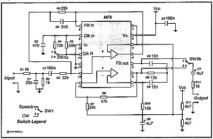
A simple circuit that can switch between a sharp cutoff frequency above 2.5 kHz and a narrow bandpass filter around 800 Hz. In the low-pass (LP) state, it is suitable for speech applications as the filter section of a...

Generating sine waves with controlled frequencies over a wide range is challenging when using RC or LC sinusoidal oscillators. However, this can be effectively achieved using a wideband digital square wave oscillator, a counter, and a weighted summing network....
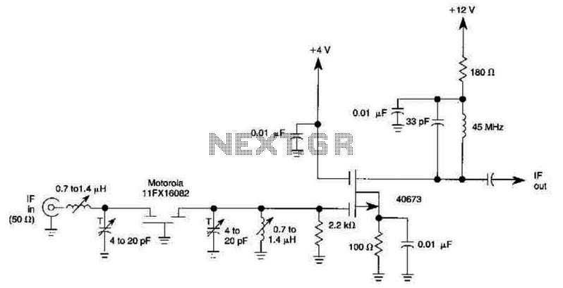
A 40673 dual-gate MOSFET is matched to a crystal filter operating at 45 MHz. The filter impedance is approximately 2 kΩ. The +4 V source can be adjusted to control the gain, ranging from +4 V to -4 V. The...
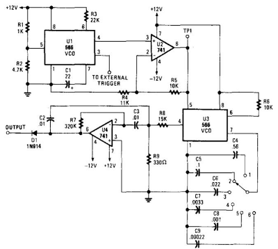
When this circuit is connected to a filter and an oscilloscope, the oscilloscope displays the filter's frequency response. A frequency that sweeps from low to high is applied to a filter. The oscilloscope is triggered by the start of...
The circuit presented operates as a bandpass filter, with the transfer function derived from FBP(s) = 1 + s/Qo + s²/w₀². The cut-off frequency, denoted as ω₀, and the quality factor (Q-factor) are defined by ω₀ = g/C and...
This circuit will filter out interference signals and ensure that the signal received from the Morse code station stands out. The described circuit functions as a signal processing system specifically designed to enhance the clarity of Morse code transmissions by...