
Multiplexed output digital camera power supply circuit composed of MAX1802
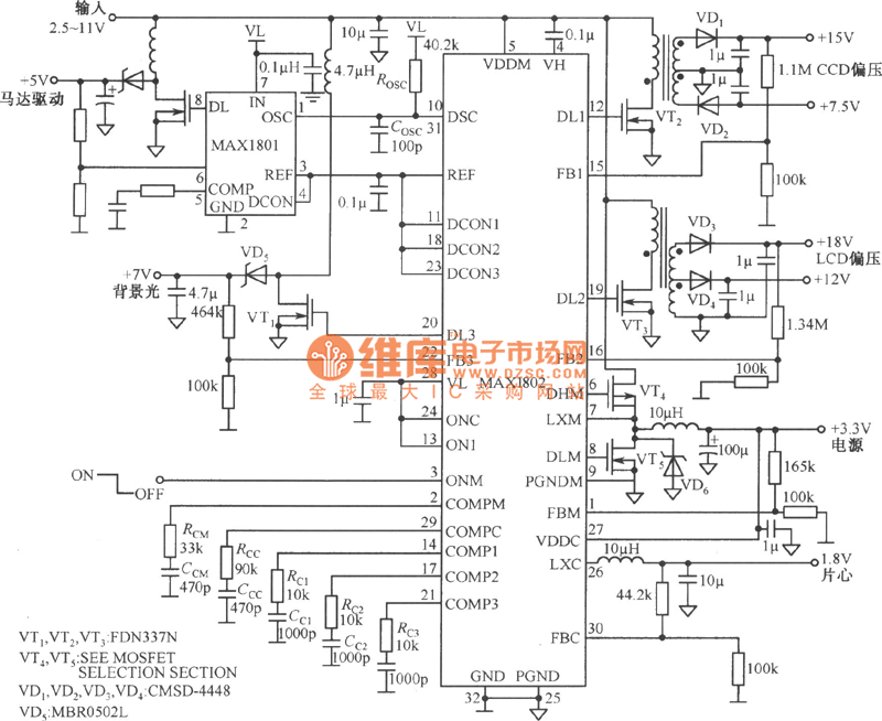
The MAX1802 is designed for applications requiring multiple output voltages, such as digital cameras, where various components operate at different voltage levels. The two buck converters step down higher input voltages to lower output voltages, while the three boost converters increase lower voltages to the necessary levels for powering specific components.
The input voltage range of 2.5 to 11V allows for flexibility in power supply options, accommodating a variety of battery configurations and other power sources. The adjustable output voltage from 2.7 to 5.5V enables compatibility with a wide range of digital camera components, such as image sensors, processors, and display modules. Additionally, the ability to set the output voltage as low as 1.25V is particularly useful for powering low-voltage components, thereby enhancing overall system efficiency.
The adjustable operating frequency of 1MHz is beneficial for optimizing the performance of the converters. A higher frequency can reduce the size of external components such as inductors and capacitors, which is advantageous in compact designs. The efficiency of the conversion process is crucial for battery-operated devices, as it directly impacts battery life and thermal performance. The MAX1802 is engineered to maintain high conversion efficiency across various load conditions, which is essential for the reliability and longevity of digital camera systems.
In summary, the MAX1802 provides a versatile and efficient solution for powering digital camera systems with multiple voltage requirements, ensuring optimal performance and adaptability in a compact design.Composed of MAX1802 multiple output digital camera power supply circuit diagram is shown as below. MAX1802 Chip has 2 buck converters and 3 boost converters. Input voltage 2.5?11V, continuously adjustable output voltage 2.7?5.5V. The lowest output voltage can be ajdusted to 1.25V. The working rate of MAX1802 can be adjusted to 1MHz and conversion efficienc.. 🔗 External reference
Related Circuits
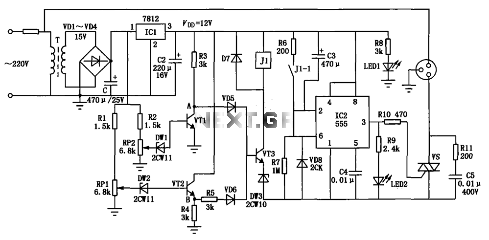
The circuit consists of a DC voltage regulator, a delay circuit, and protection mechanisms for overvoltage and undervoltage. It utilizes the LM7812 integrated voltage regulator to provide a stable 12V output. The protection circuit samples voltage using R2 and...
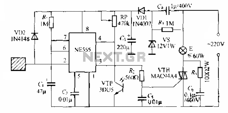
The circuit utilizes a NE553 automatic light sensor composed of 55 groups, allowing lights to turn on when individuals are present and turn off when they leave. The power supply includes VD1, vS, and C, with a 12V DC...
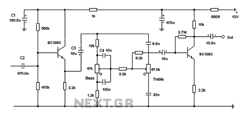
Based on the classic Baxendall tone control circuit, this design offers a maximum cut and boost of approximately 10 dB at 10 kHz and 50 Hz. Since the controls are passive, the final transistor provides a slight boost. The...
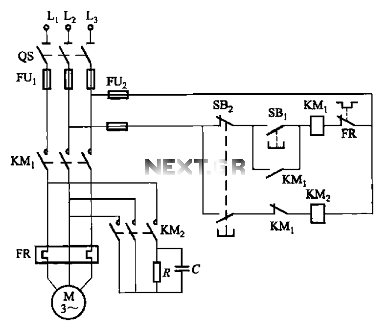
The 3F155 circuit, as depicted in the provided figure, operates in manual control mode. It features a self-excitation braking phase, while the other two phases utilize a short brake. A resistor (R) is involved, along with the voltage across...
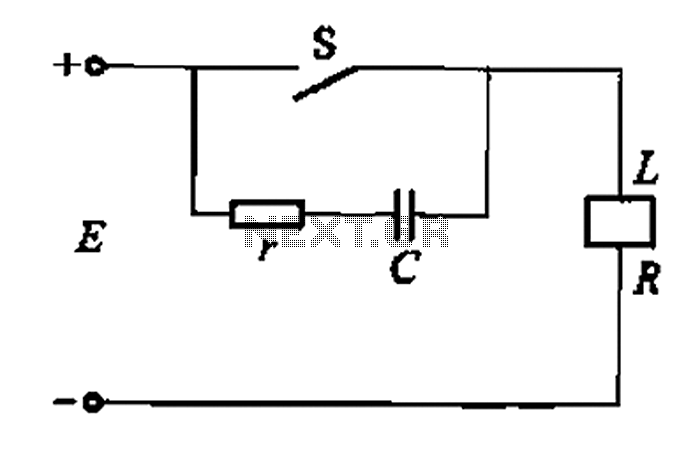
A resistor-capacitor circuit designed to prevent spark blowout. The coil's magnetic energy is converted into electrical energy stored in the capacitance C, effectively suppressing sparks and enhancing safety. The circuit is capable of functioning normally even with reverse polarity....
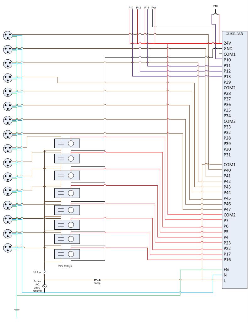
This is the circuit diagram for the Comfile CUSB-36R Programmed Christmas Lights. If it is difficult to read, please contact me via email at [email protected], and I will provide a more detailed schematic. The Comfile CUSB-36R can either drive...
Warning: include(partials/cookie-banner.php): Failed to open stream: Permission denied in /var/www/html/nextgr/view-circuit.php on line 713
Warning: include(): Failed opening 'partials/cookie-banner.php' for inclusion (include_path='.:/usr/share/php') in /var/www/html/nextgr/view-circuit.php on line 713