
Volume control circuit
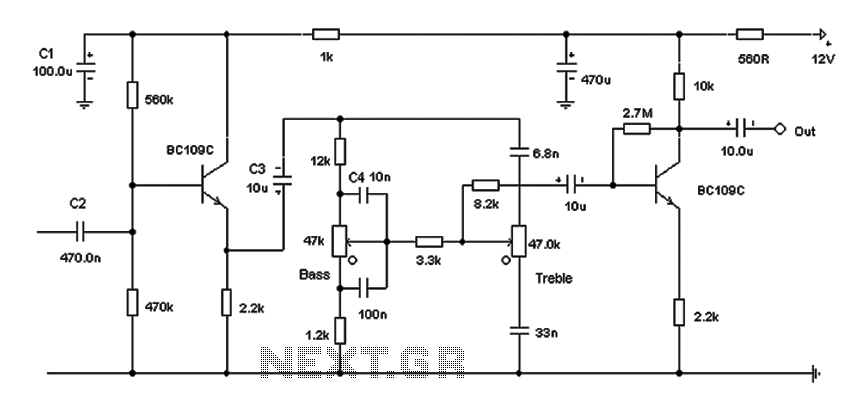
The Baxendall tone control circuit is a widely recognized design utilized for adjusting the tonal quality of audio signals. The circuit typically consists of two primary controls: one for bass frequencies and another for treble frequencies. In this specific implementation, the circuit achieves a maximum cut and boost of around 10 dB, which is effective at both 10 kHz and 50 Hz, allowing for significant tonal adjustments without introducing excessive distortion.
The passive nature of the tone control means that the adjustments made by the user will not amplify the signal on their own; however, the inclusion of a final transistor stage compensates for this by providing a slight gain. This transistor serves to buffer the output, ensuring that the signal remains strong enough to drive subsequent audio processing equipment, such as amplifiers.
The output stage is designed with compatibility in mind, targeting amplifiers with input impedances between 10 kΩ and 250 kΩ. This range is crucial, as it ensures that the tone control circuit can interface effectively with a variety of audio amplifiers without compromising sound quality or signal integrity. Proper impedance matching is essential for minimizing signal loss and maintaining the desired audio characteristics.
In summary, this Baxendall tone control circuit is an effective solution for audio applications requiring flexible tonal adjustments while preserving signal strength and clarity. Its design allows it to be easily integrated into a range of audio systems, enhancing the overall listening experience. Based on the classic Baxendall tone control circuit, this provides a maximum cut and boost of around 10dB at 10K and 50Hz. As the controls are passive, the last transistor prov ides a slight boost. The output is designed to feed an amplifier with input impedance of 10k to 250k.
Related Circuits
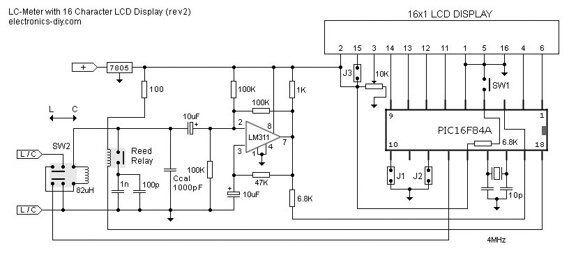
This is one of the most accurate and simplest LC inductance/capacitance meters available, which can be easily constructed by an individual. This LC meter is capable of measuring very small inductances ranging from 10 nH to 1000 nH, 1...
The double-ended working core square wave inverter transformer area product formula Bm represents the maximum magnetic flux. The primary side of the transformer features switches S1 and S2 in parallel with IRF32055. This parallel configuration is primarily due to...
Each step will result in a self-functional unit. By the end of this process, it will be possible to link the steps together into a powerful FM transmitter. This section will explain the main controlling unit for the FM...

The objective of the circuit is to create an electronic dice using the functionality of a 555 timer integrated circuit operating in astable mode. The electronic dice circuit utilizes a 555 timer configured in astable mode to generate a series...
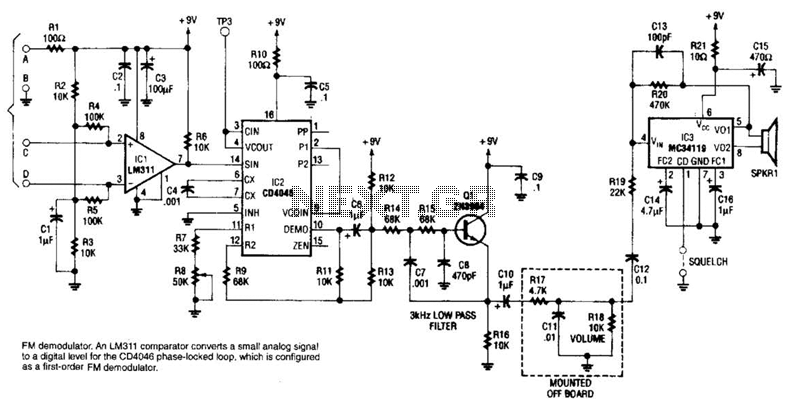
An LM311 comparator converts a small analog signal to a digital level for the DC4046 phase-locked loop, which is configured as a first-order FM demodulator. This demodulator operates with a 50-kHz FM modulated input signal and has applications in...
This project is an audio amplifier designed to amplify output signals from small radios, tape players, CD players, or other audio signal sources. For stereo operation, two identical amplifiers must be constructed—one for the left channel and another for...