
Music/Sound Controlled Disco Light
The circuit operates by utilizing the reactance of capacitor C1 to reduce the mains voltage without generating excess heat, which is a significant advantage in terms of efficiency. The capacitor's reactance effectively limits the current flow, allowing for a safe voltage reduction. Following this, the reduced AC voltage is directed to diodes D1 and D2, both of which are 1N4007 components. These diodes serve to rectify the AC voltage into a pulsating DC voltage, ensuring that the output is suitable for further processing or usage in DC applications.
The output voltage is then clamped to 24V, which is achieved through the use of additional components, likely involving a voltage regulator or zener diode in conjunction with the rectification stage. This clamping mechanism ensures that the voltage does not exceed the desired level, providing a stable output that can be utilized for powering electronic devices or circuits that require a consistent voltage supply.
In summary, this circuit effectively reduces mains voltage through capacitive reactance, rectifies it using robust diodes, and clamps the output to a safe, usable level of 24V, ensuring both efficiency and reliability in operation.The mains supply can be conveniently reduced with no heat dissipation by the reactance of C1; then rectified by D1 (1N4007) and D2 (1N4007) and clamped to 24V.. 🔗 External reference
Related Circuits
A useful operation for the cars is delayed extinguishing internal lighting cabin of passengers, after close some door of car. Certain cars allocate this operation from their constructor. Oldest sure do not allocate such operation. This delay makes this...

The circuit below turns on a light corresponding to the first of several buttons pressed in a "Who's First" game. Three stages are shown but the circuit can be extended to include any number of buttons and lamps. Three...
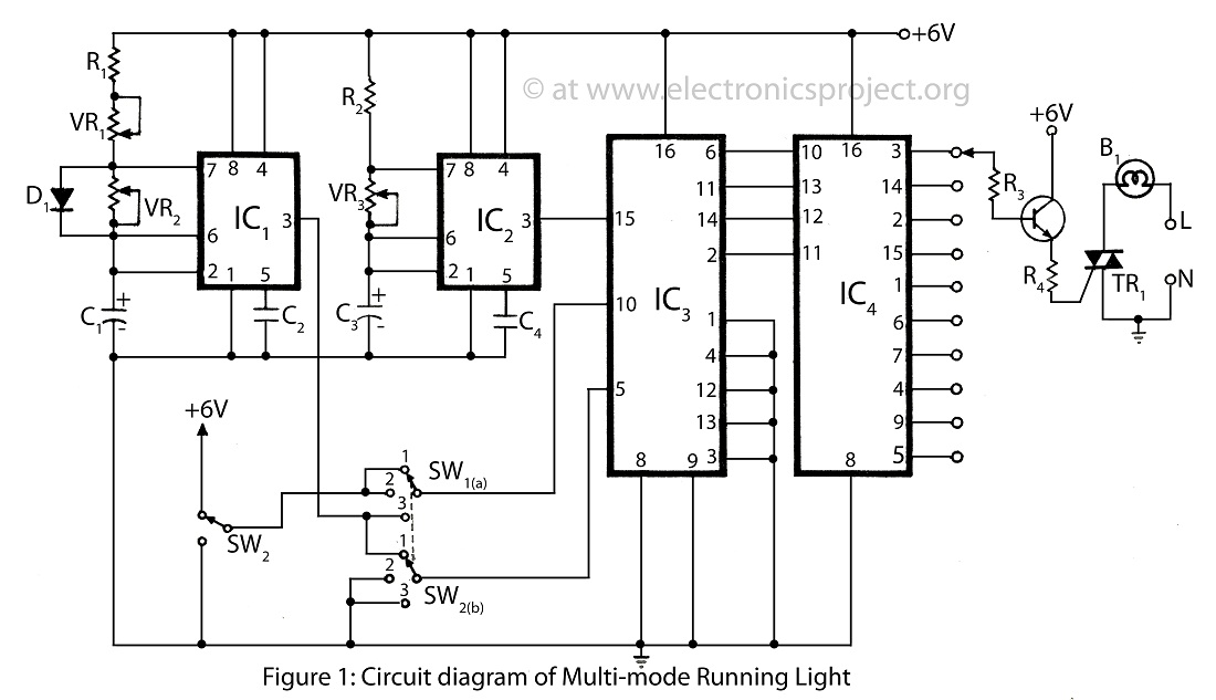
The multi-mode running light presented on this website features a simple circuit diagram designed for a bidirectional operation. It supports three different modes, making it a versatile addition to various electronics projects. The multi-mode running light circuit is designed to...
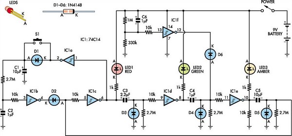
This toy traffic signal utilizes a single, cost-effective hex Schmitt-trigger inverter IC (IC1a-IC1f) to directly control three colored LEDs (red, green, and amber). Upon activation, the circuit illuminates the red signal for 30 seconds, followed by the green signal...

One reason why commercial soldering stations are expensive is that they typically require soldering irons with built-in temperature sensors. Commercial soldering stations are designed to provide precise temperature control and consistency during soldering operations, which is essential for achieving reliable...

This colorful backlit aquarium light provides a natural appearance to the aquarium tank. The aquarium LED lighting circuit automatically turns on at sunset. The aquarium LED lighting system enhances the aesthetic appeal of the aquarium by simulating natural lighting conditions....