
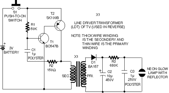
Car central Light Dimmer

The circuit described facilitates a delayed extinguishing function for the interior lighting of a vehicle after the closing of a door. It is particularly beneficial for older car models that do not have this feature integrated. The primary component of the circuit is a delay mechanism that controls the duration for which the internal lamp (L1), typically rated at 12V and 10W, remains illuminated after a door is closed.
The operation of the circuit can be summarized as follows: the system employs a switch (S1) that allows the user to select different modes of operation. In the first mode (place A), the lamp L1 is continuously on, as the switch connects to the ground (0V). In the second mode (place B), the lamp is off, and in the third mode (place C), the lamp remains on as long as any door is open, due to the door switches providing a ground signal to the lamp.
When a door is closed, the corresponding door switch opens, but the capacitor (C1) remains charged. The discharge of C1 through transistor Q1 activates transistor Q4, allowing the lamp L1 to remain illuminated for a certain time period, determined by the resistance of the trimmer resistor (TR1). The discharge time of C1 can be adjusted by varying the resistance value of TR1, thus controlling how long the lamp stays on after the door closes.
In many vehicles, lamp L1 is connected in parallel with the dashboard door indicator lamp, which also remains illuminated for the same duration, providing a visual indication of the door's status.
It is important to ensure that transistor Q4 is mounted on a heat sink to prevent overheating and that the circuit is properly insulated to avoid short circuits with the vehicle chassis. The components used in the circuit include transistors (Q1=BC547B, Q3=BD140, Q4=BD243C), diodes (D1=1N4148, D2=1N4002), a capacitor (C1=47uF 25V), resistors (R1-2=2.2Kohms, R3=33Kohms), a fuse (F1=2A Fast), and a 2-pin connector (J1). The trimmer resistor (TR1) is specified as 47 ohms for fine-tuning the delay feature. Proper placement and insulation of these components are crucial for the reliable operation of the circuit in an automotive environment.A useful operation for the cars is delayed extinguishing internal lighting cabin of passengers, after close some door of car. Certain cars allocate this operation from their constructor. Oldest sure do not allocate such operation. This delay makes this circuit. In the scheme appears the delay circuit as well as a typical circuit of connections of lamp L1, usually 12V 10W, with the switch S1 choice of lamp operation.
In place A the lamp L1 remains continuously turned on, because the switch is in the place of 0V. In place B the lamp it remains off and in place C the lamp it turns on and she remains turned on all hour some door is open, hence somebody from the switches that are found in each door have closed have given the 0V in the lamp. If now the door close, the corresponding switch go open, but the C1 is already charge, discharge by the Q1 and makes the Q4 close.
Thus lamp its load anymore in the Q4 that follows the rhythm of C1 discharge. The time discharge of C1 depends from the resistance of TR1, with that we can change the time that will remain turned on the lamp L1 afterwards the close of some door of car. In a lot of cars the lamp L1 found in parallel connection with the indicative lamp, open door that is found in the automotive dashboard.
Thus you will observe this indicative lamp remains also turned on afterwards the door close and follows the course of lighting of lamp L1. This is a " failing" of circuit. Transistor Q4 should be placed on one small piece of aluminum and it will be supposed insulated from this.
The circuit after it is regulated with the TR1 in the time that you wish should insulated well, so that short-circuit his some point with the chassis of automotive and it is placed with small length of cables somewhere near in the unit of lamp L1. Q1-2=BC547B D2=1N4002 C1=47uF 25V Q3=BD140 R1-2=2.2Kohms 1/4W F1=Fuse 2A Fast Q4=BD243C R3=33Kohms 1/4W J1=2PIN Connector D1=1N4148 TR1=47ohmsK trimmer
🔗 External reference
Related Circuits
The anti-theft system includes two frequency sirens connected to the vehicle's immobilizer system. In the laboratory simulation model, the changes in operating modes, siren activation, and fuel supply cut-off are indicated by the illumination of LEDs and communicated to...
Multisim is circuit simulation software based on SPICE, which stands for Simulation Program with Integrated Circuit Emphasis. Developed in 1975 at the University of California, Berkeley, it focuses on simulating integrated circuits. In Multisim 9, the MultiMCU module must...
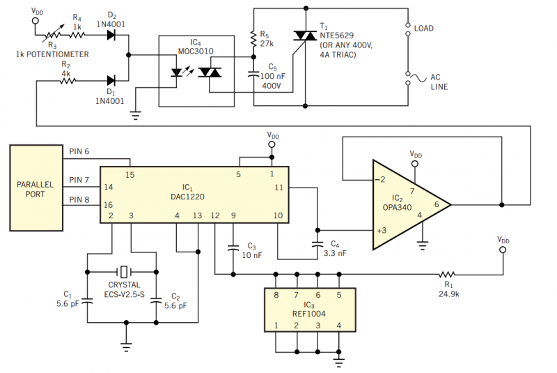
Using the simple circuit in Figure 1, you can control the light intensity in your room or work area from your PC. The heart of the circuit is a low-power D/A converter that converts digital words from a computer's...
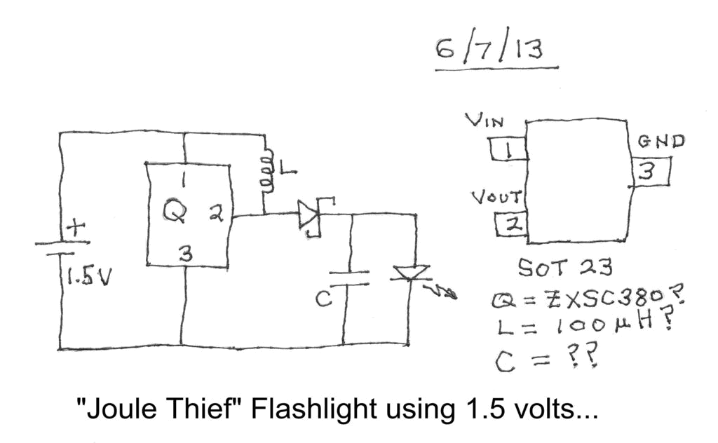
Investigating a Paradox: Recently, an energy-saving LED flashlight was observed for sale that utilized only one 1.5-volt battery. Upon purchasing this light and disassembling it, the expectation was to find a battery, bulb, switch, and a circuit board designed...
This circuit operates on 12V DC instead of mains AC. This is an advantageous approach for those who prefer not to deal with circuits connected directly to mains voltage or wish to power the stroboscope using batteries. Flash Slave...
A high performance op-amp that sets a new standard of excellence in noise performance only 0.9nV/Hz with low source resistances. Total harmonic distortion is less than 0.01%. The op-amp is suitable for use in high quality audio, low noise...