
Musical envelope generator and modulator
The circuit described operates as an envelope generator with a modulation function, primarily used in audio synthesis and sound design applications. The key components include Q1 and Q2, which are likely bipolar junction transistors (BJTs) or field-effect transistors (FETs), depending on the design requirements. The attack and decay pots serve as variable resistors, allowing for fine-tuning of the time constants associated with the envelope's rise and fall.
The attack time, controlled by the resistance value of the attack potentiometer and the series resistor, directly influences how quickly the output signal reaches its maximum amplitude after the gate voltage is applied. A lower resistance value results in a quicker charge time for capacitor C, producing a sharp, percussive sound. Conversely, a higher resistance value leads to a slower charge time, creating a sound that resembles a reverse envelope.
Upon the release of the gate voltage, Q2 becomes active, allowing capacitor C to discharge through the decay potentiometer. This discharge process determines how quickly the envelope falls back to zero, contributing to the overall character of the sound. The buffered envelope from IC1 is then fed to Q3, where it is modulated by the square wave input. The square wave's frequency dictates the chopping rate of the envelope, effectively creating a rhythmic pulsing effect in the audio output.
The output waveform combines the dynamic envelope shape with the harmonic content of the square wave, resulting in a rich and complex sound. IC2 acts as a buffer to ensure signal integrity, preventing loading effects that could distort the output. The diode D1 plays a critical role in managing the envelope's decay, ensuring that the signal smoothly transitions to silence at the end of a note, thus enhancing the overall musicality of the circuit.
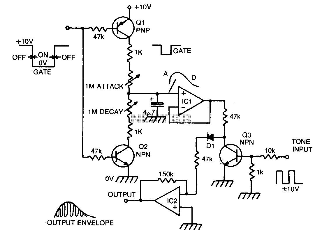
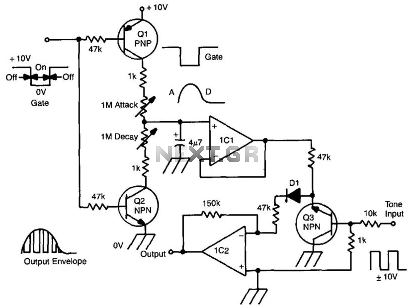
This envelope generator circuit is versatile and can be employed in various synthesizer applications, allowing for expressive sound shaping capabilities. By adjusting the attack and decay parameters, users can achieve a wide range of auditory effects, from sharp percussive hits to smooth, evolving tones.When a gate voltage is applied, Ql is turned on and capacitor C is charged via the attack pot in series with the 1 K resistor varying this pot, attact time constant. A fast attack gives a percussive sound, a slow attack the affect of "backward" sounds. When the gate voltage returns to its off state, Q2 is turned on and capacitor is discharged via decay pot to ground.
The envelope is buffered by ICl and applied to Q3, which is used as a transistor chopper. A musical tone in the form of a squarewave is connected to the base of Q3 This turns the transistor on or off and thus the envelope is chopped up at regular intervals, the intervals being determined by the pitch of the squarewave. The resultant waveform has the amplitude of the envelope and the harmonic structure of the squarewave.
IC2 buffers the signal and Dl ensures that the envelope dies away at the end of a note. 🔗 External reference
Related Circuits

Generators that do not use fuel to operate provide 24 hours of electricity for continuous use. In the early days of this invention, a significant issue arose: the battery powering the generators would deplete within 20 to 30 minutes...
This circuit utilizes the versatile MAX038 function generator. While some advanced features of this IC are disabled in this configuration, it is capable of generating sine, triangle, and square waves by adjusting the A0 and A1 pins (refer to...
Many applications require low-frequency signal generators that can deliver high-performance, high-resolution signals. This design idea presents a circuit that generates frequencies from 0 to 1 MHz, providing sinusoidal, triangular, and square-wave outputs with frequency resolution better than 0. A...
A gate voltage is applied to initiate the process. When the gate voltage is in the ON state, Q1 is activated, and capacitor C is charged through the attack potentiometer in series with the 1 kΩ resistor. By adjusting...

Utilize the Maxim MAX292 switched-capacitor filter integrated circuit to convert a square wave into a sine wave. The operational frequency range of the circuit spans from 5.2282 Hz to 8928.6 Hz when the microcontroller is functioning at a 16-MHz...
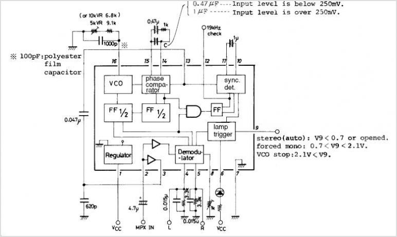
The LA3370 is a multiplex integrated circuit (IC) designed for FM car stereo applications. It performs two primary functions using the intermediate frequency (IF) meter output voltage: 1. Stereo Noise Control (SNC), which effectively reduces noise specific to FM...