
Adjustable High/Low Frequency Sine wave generators
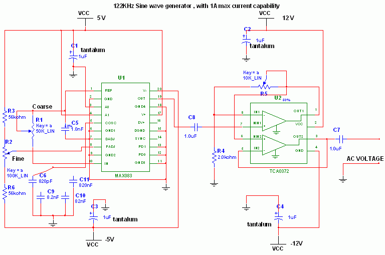
The MAX038 function generator is a highly capable integrated circuit that allows for the generation of various waveforms with precise frequency control. In this specific application, the circuit's design emphasizes the importance of monitoring the ESR of electrolytic capacitors, which can be critical in ensuring the reliability of electronic devices. The choice of 122 kHz is strategic, as it keeps reactance low, facilitating accurate ESR measurements.
The use of a precision resistor for current measurement ensures that the voltage drop across the capacitor can be accurately interpreted in relation to the current flowing through it. This relationship is fundamental for calculating ESR, which is a key parameter in assessing capacitor health. The design allows for flexibility in frequency generation through the use of a multiposition switch, which can accommodate a variety of capacitor values, thus enabling the user to select the desired frequency range easily.
The TCA0372 op-amps play a crucial role in amplifying the output signal from the MAX038, providing the necessary gain to make the measurements more discernible. The buffer stage ensures that the output signal remains stable and is not affected by subsequent circuit loading.
For operational stability, the circuit's power supply requirements are well-defined, emphasizing the need for multiple voltage levels to support the different components effectively. The inclusion of smoothing capacitors and voltage regulators ensures that the circuit operates within specified voltage ranges, which is essential for maintaining performance and accuracy.
This circuit exemplifies a practical application of function generators in electronic testing and diagnostics, demonstrating how integrated circuits can be utilized to create effective measurement tools in the field of electronics.This circuit uses the versatile MAX038 function generator. Although in this circuit some of the advanced characteristics of this IC are disabled, you can generate Sine, Triangle, Square waves (adjusting A0 and A1 pins see datasheet on if you want other waves, use a switch). I selected this particular frequency (122 Khz) because i needed a cheapo ESR-o-meter for my electrolytic capacitors to monitor their health as they have to discharge tens of amperes in less than 2 ms. At 122 KHz capacitive reactance is very low, and inductive reactance isn`t so high, so forcing a current (es 200mA, using a precision resistor) through a capacitor and reading AC voltage drop accross it gives me an estimation of ESR (Vdrop/current).
Of course inductive and capacitive reactance are still present, but negligible. The 122 khz 2V p-p sine wave is generated by the MAX038 IC, its frequency can be calculated by the formula Freq (MHz) = Iin(uA) / C6 (pf). Iin = 2, 5V / R1 (25Kohm default). So the freq is 0, 122 MHz. The resistor is for small adjustments, don`t go under 10000 Kohm or above 40000 Kohm because the accuracy will drop.
If you want multifrequency just use the multiposition switch with 820 pF, 8, 2 nF, 82nF, 820 nf for 122Khz range 12, 2Khz range 1220 Hz and 122 Hz. Fine tuning can be done adjusting R2, the frequency can vary from 1, 7x (Vfadj = -2, 4) to 0, 3x (Vfadj = 2, 4) of the main frequency (when fadj is at 0V).
The sine wave output is feed into a TCA0372 1/2 opamp to achieve a gain from 1 to 5 (2V p-p, 10 V p-p), adjust the potenziometer and into a TCA0372 2/2 opamp buffer stage also present on the same IC. Adjusting the frequency needs a frequency counter, so this circuit should be used on conjunction with a freq couter.
The max current is 1A, but i would suggesto to not go above 0, 5A to remain accurate. Needs a computer power supply with 12V, 5V, -5V, -12V, GND to be operated, if you don`t have one just use a multivoltage mains transformer (15 watt is enough) diode bridges (low current 1-2 Amps), smoothing capacitors 10000uF 16V, and voltage regulators such as LM7905 and LM7912. 🔗 External reference
Related Circuits

A simple frequency meter or frequency counter circuit featuring an LCD display and an AVR microcontroller. This includes a DIY schematic circuit diagram and embedded C code. The frequency meter circuit is designed to measure the frequency of input signals...
This circuit consists of a UJT oscillator in which the timing charge capacitor C2 is linearly dependent on the input signal voltage. The charging current is set by the voltage across resistor R5, which is accurately controlled by the...
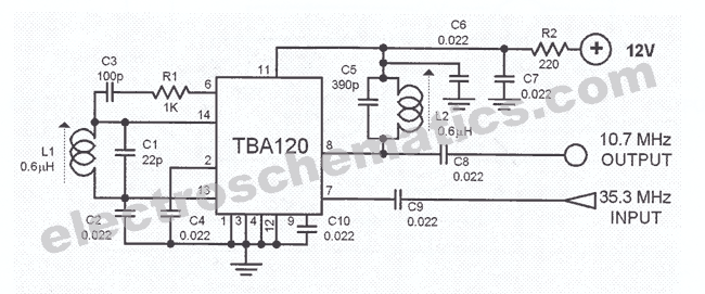
This is a 35.3 to 10.7 MHz converter circuit. It converts the 35.3 MHz signal coming from a VHF/UHF tuner down to an FM tuner to decode the TV audio in FM. The 35.3 to 10.7 MHz converter circuit is...
This text outlines preliminary plans for a frequency meter designed for a bat detector. The device measures the frequency of the local oscillator in a heterodyne type bat detector, serving as a valuable tool for bat identification. The frequency...
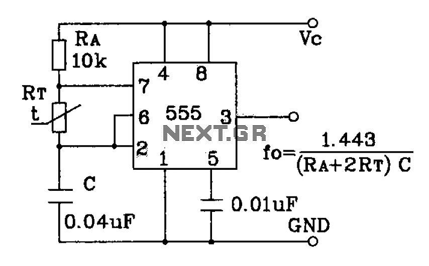
555 precision temperature sensor with temperature frequency converting circuit diagram consisting of: The 555 precision temperature sensor operates by converting temperature variations into frequency signals. This circuit typically utilizes a 555 timer IC configured in astable mode to generate...
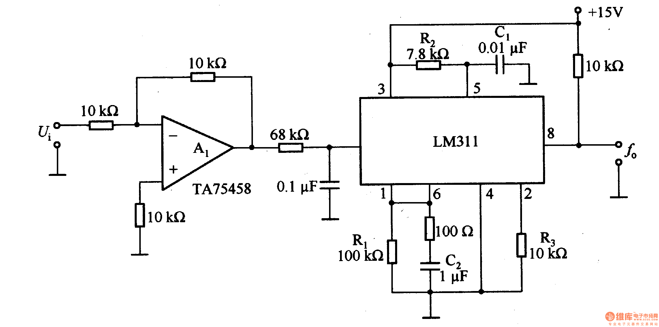
The LM311 is an integrated circuit that functions as a reference voltage generator, comparator, amplifier, and discharge circuit. It is designed for ease of use. In the circuit, the output frequency f0 is... The LM311 is a versatile integrated circuit...