
mxr micro amp true bypass
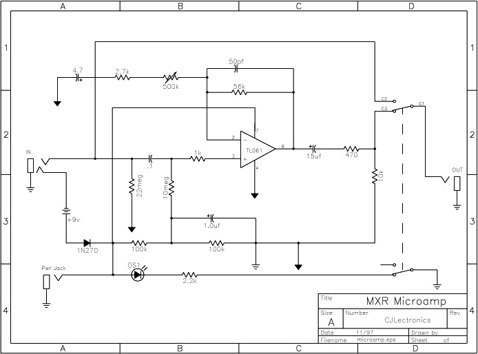
The modification of the MXR Micro Amp to achieve true bypass switching is a common enhancement for guitar pedal enthusiasts seeking to improve the tonal integrity of their signal chain. The original design incorporates a surface-mounted double pole double throw (DPDT) switch, which complicates the modification process.
To implement true bypass, the circuit board must be carefully reworked to accommodate a new switching mechanism that allows the input signal to bypass the effect circuit entirely when the pedal is disengaged. This typically involves desoldering the existing DPDT switch and replacing it with a more accessible switch type, such as a standard footswitch or a toggle switch, which can be mounted externally.
The process begins by identifying the input and output paths on the circuit board, as well as the points where the switch connects to the circuit. It is essential to take detailed notes or photographs of the original connections to ensure accurate reconnection after the modification. Once the original switch is removed, the new switch's pin configuration must be matched to the circuit requirements, ensuring that it can handle the signal levels without introducing noise or distortion.
In addition to the switch replacement, it may be necessary to reroute traces on the circuit board to support the new bypass configuration. This can involve cutting existing traces and soldering new jumper wires to maintain the integrity of the circuit. Care must be taken to avoid damaging other components on the board during this process.
After the modification is complete, it is advisable to test the pedal in various configurations to ensure that the true bypass function operates correctly and that the overall performance of the pedal is maintained or enhanced. Proper shielding and grounding should also be considered to minimize any potential interference that could affect the signal quality.Modifying the MXR Micro Amp for True Bypass switching, requiring tricky circuit board surgery due to its original surface-mount DPDT switch.. 🔗 External reference
Related Circuits
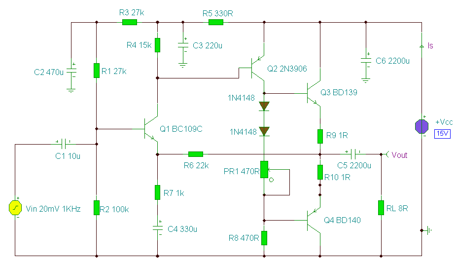
A 2 Watt audio amplifier made from discrete components. This was one of the earliest circuits that I ever designed and built, in Spring 1982. At that time I had only an analogue meter and a calculator to work...
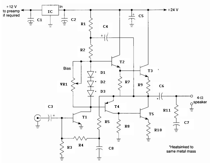
A 10 Watt audio amplifier circuit diagram is presented. This circuit serves as a general-purpose 10-W power audio amplifier, suitable for medium power applications or for use in modulation within AM transmitters. To achieve higher power levels, up to...
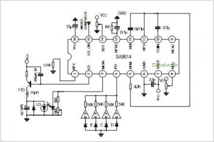
The SA9618A is designed for ALPC and signal conversion between a CD optical pickup and a decoding chip. This integrated circuit (IC) features an interconnection for a general CD optical pickup photodiode bias voltage VREF generation circuit, an RF...
This design utilizes a well-established circuit topology for the power amplifier, employing a single-rail supply of approximately 60V and capacitor coupling for the speakers. The advantages of this configuration for a guitar amplifier include a straightforward circuit design, even...
This UHF wideband amplifier (Ultra High Frequency amplifier) provides a total gain of 10 to 15 dB in the frequency range of 400 to 850 MHz, making it suitable for areas with weak TV signals. For optimal performance, the...
Build a 20 Amp 13.8 Volt Power Supply. There are some electronic applications where it may be necessary to run relatively high current circuits, such as transformers. To construct a 20 Amp, 13.8 Volt power supply, the following components and...