
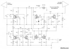
10 Watt Audio Amplifier
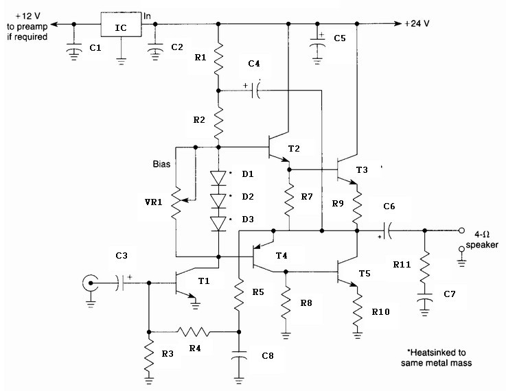
The 10 Watt audio amplifier circuit typically consists of a few key components: a power supply, transistors, resistors, capacitors, and possibly a heat sink for thermal management. The power supply provides the necessary voltage and current to drive the amplifier. The transistors, which can be configured in a push-pull arrangement, serve as the main amplifying elements, allowing the circuit to boost the audio signal's power level effectively.
Resistors in the circuit are used to set the biasing conditions for the transistors, ensuring they operate in the appropriate region of their characteristics for linear amplification. The bias resistor value is crucial, as it directly influences the circuit's performance and maximum output power. By adjusting this resistor, one can optimize the amplifier for different applications, whether for standard audio amplification or for modulation in AM transmission.
Capacitors are employed for coupling and decoupling purposes, ensuring that AC signals pass through while blocking DC components that could affect performance. Additionally, capacitors help in stabilizing the power supply, filtering out noise that could distort the audio signal.
For applications requiring higher power output, the circuit can be modified by increasing the supply voltage. However, care must be taken to ensure that the transistors can handle the increased voltage and current without overheating or becoming damaged. This is where the selection of a suitable heat sink becomes important, as it dissipates heat generated during operation, maintaining the reliability and longevity of the amplifier.
In summary, the 10 Watt audio amplifier circuit is a versatile design that can be adapted for various applications, including audio amplification and AM modulation. By understanding the relationships between the components and their configurations, one can effectively tailor the circuit to meet specific power requirements while ensuring optimal performance.10 Watt Audio Amplifier circuit diagram. This is general purpose 10-W power audio amplifier circuit for medium power amplifier or use a modulation in the AM transmitter. For higher power up to 30 W can be obtained by increasing the voltage and change the bias resistor value.
🔗 External reference
Related Circuits

This car audio amplifier circuit is based on the LA47536 audio amplifier integrated circuit designed by Sanyo. This audio amplifier circuit is specifically designed for car audio power amplifiers. The LA47536 car audio amplifier IC features four output channels...
The 2SK2975 has reportedly been discontinued by the manufacturer, with the RD07MVS1 from Mitsubishi serving as its replacement. This new device is very similar but appears to have slightly higher gain—10 dB typical at 520 MHz compared to 8.4...
This simple circuit mixes two or more channels into one channel (eg. stereo into mono). The circuit can mix as many or as few channels as you like and consumes very little power. The mixer is shown with two...
The distortion produced by a typical solid-state Class-B power amplifier consists of eight mechanisms, all of which may coexist and whose distortion products overlap to create a complex result. Methods for isolating each mechanism for study and minimizing its...
The PT2399 digital echo circuit schematic is an electronic design that utilizes the PT2399 integrated circuit (IC) for audio applications. This digital echo processor, based on CMOS technology, incorporates both analog-to-digital conversion (ADC) and digital-to-analog conversion (DAC) processes for...
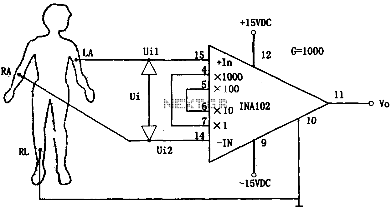
This document outlines a preamplifier circuit designed for measuring human biological signals, such as ECG and EEG. These biological signals are typically weak and require high amplification circuits. The circuit utilizes a low-power integrated operational amplifier, INA102. The INA102...