
Wideband UHF Amplifier - Antenna TV Amplifier Circuit
The UHF wideband amplifier is designed to enhance weak television signals in the specified frequency range. Its architecture typically includes a series of low-noise amplifying stages to achieve the specified gain while maintaining signal integrity. The choice of SMD capacitors (C1, C2, C6, and C7) is crucial, as these components help filter out unwanted frequencies and stabilize the amplifier's performance.
The metal enclosure serves multiple purposes: it protects sensitive electronic components from external interference and environmental factors, and it helps to minimize electromagnetic interference (EMI) that could degrade the amplifier's performance. Proper grounding of the enclosure is essential to ensure effective shielding.
The power supply, rated at 12V, should be stabilized to prevent voltage fluctuations that could affect the amplifier's performance. The inclusion of a 10 to 100 µH coil on the power line is a critical design feature; it acts as an inductor that filters out high-frequency noise from the power supply, ensuring that only the desired signals are amplified.
Connecting the amplifier to the TV set through a coupling capacitor is a common practice in RF design. This capacitor allows AC signals to pass while blocking DC components, preventing potential damage to the TV’s circuitry. The amplifier should be carefully calibrated to optimize the gain and ensure that the output signal is within the acceptable range for the connected TV.
In summary, the design and implementation of a UHF wideband amplifier involve careful consideration of component selection, housing, power supply design, and signal coupling techniques to achieve reliable performance in enhancing weak TV signals.This UHF wideband amplifier(Ultra High Frequency amplifier) has a total gain of 10 to 15 dB in the 400 850 MHz domain frequency so it can be used where the tv signal is weak. For this UHF antenna tv amplifier to work correctly you need to cut the components pins as short as possible.
C1, C2, C6, C7 are SMD type ( surface mounted ). This antenn a tv amplifier or uhf wideband amplifier need to be build inside of a metal box and then connected close to the tv antenna. The power supply is a simple 12V stabilized source. The antenna tv amplifier can be connected directly to the power supply thru coaxial cable of the tv antenna but you need a 10 100uH coil on the alimentation line.
The tv set will be connected to the uhf amplifier thru a small coupling capacitor. 🔗 External reference
Related Circuits
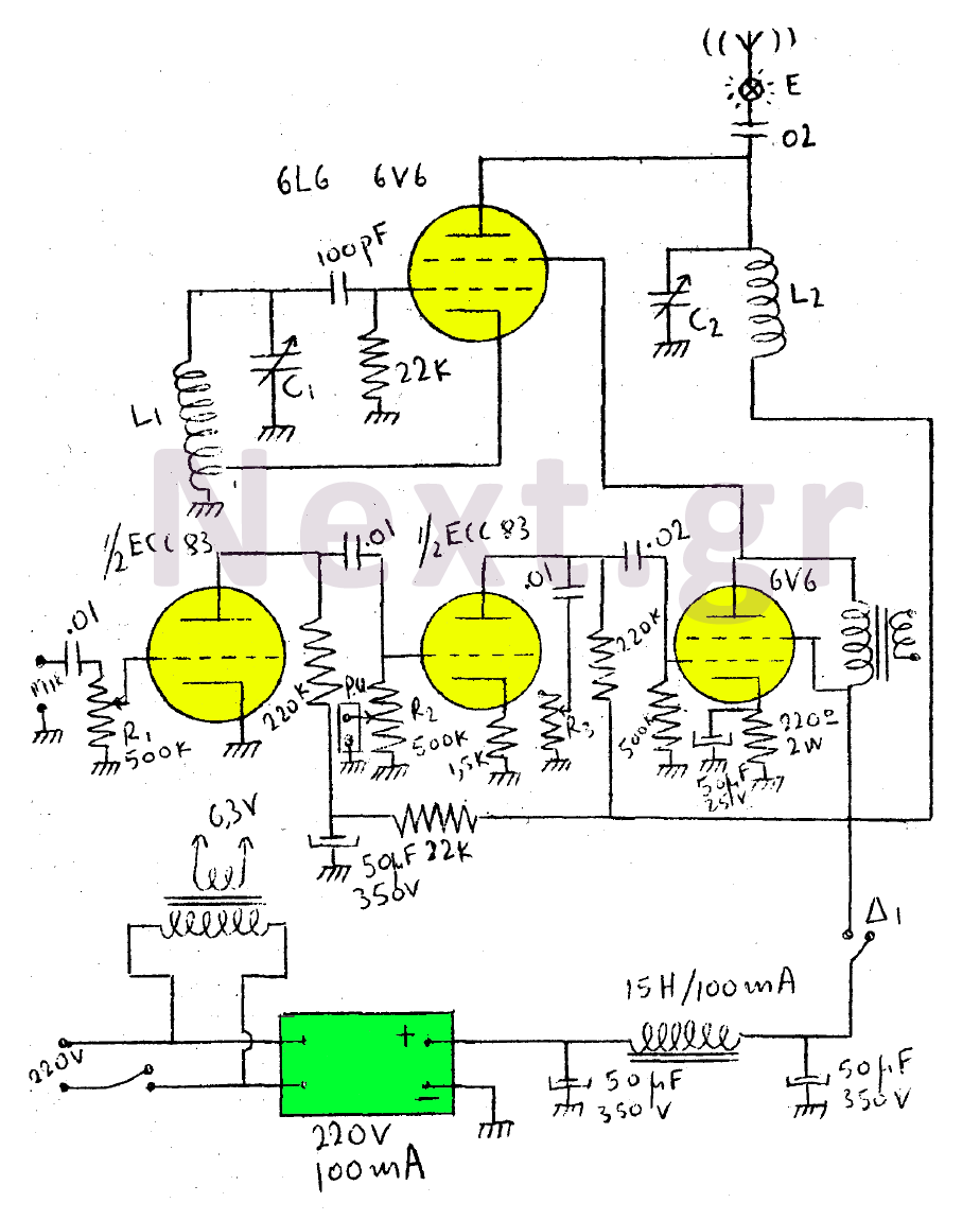
This circuit features a wearer assembly that includes a single lamp, either a 6V6 or 6L6, functioning as both an oscillator and an output amplifier. Coil L1 serves as the medium wave oscillation coil, while coil L2 is composed...
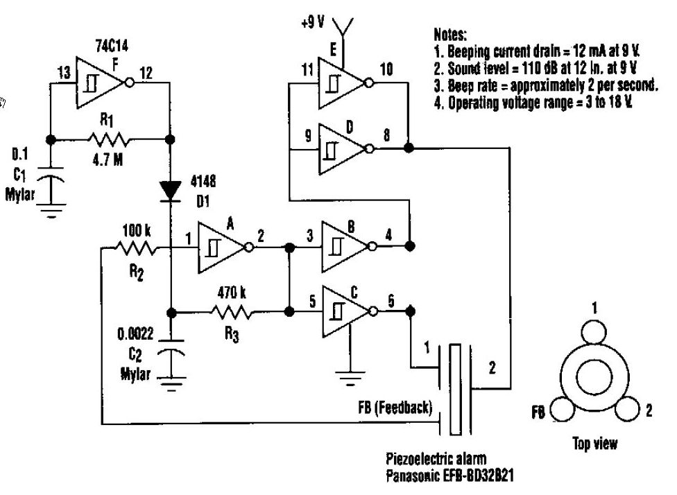
This beeper circuit generates an impressive 110dB sound level from a 9V supply. The design employs a single 74C14 (CD40106B) CMOS hex inverting Schmitt-trigger integrated circuit (IC), which must be paired with a piezoelectric device featuring a feedback terminal....
This circuit resembles an LED clock but utilizes 12 neon indicator lamps in place of LEDs. It operates on two high-capacity nickel-cadmium cells (2.5 volts), providing power for several weeks. A small switching power supply generates the high voltage...
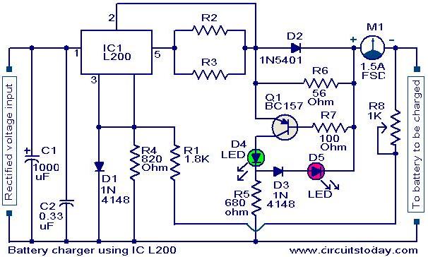
A simple battery charger circuit with reverse polarity indication is presented here. The circuit utilizes the L200 integrated circuit (IC), which is a five-pin variable voltage regulator. The charging circuit can be powered by DC voltage from either a...
This is a transistor inverter circuit diagram rated for 100 watts, designed as an easy-to-build circuit. It utilizes only transistors and does not incorporate any integrated circuits. The circuit converts a 12V battery input to a 220V, 50Hz square...

This circuit exhibits an exceptionally fast high-frequency response, as demonstrated by applying a 100 kHz square wave to the input. All graphs were produced using Tina Pro. The circuit's design is optimized for high-frequency applications, showcasing rapid response times that...