
Ne602 Superhet Front End Circuit
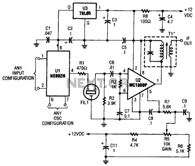
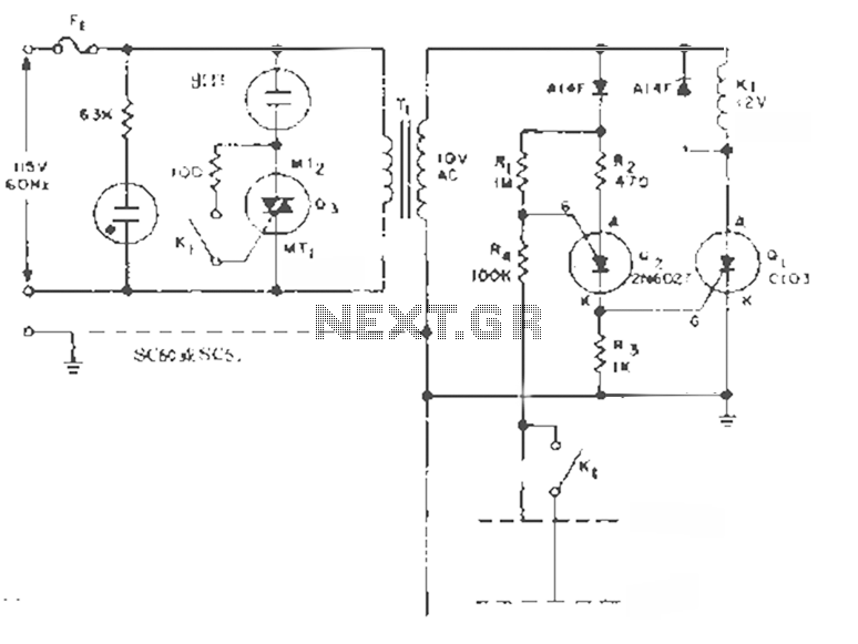
The described circuit utilizes the NE602 integrated circuit, which functions as a mixer and oscillator, in conjunction with an MC1350P integrated circuit, which serves as a low-noise amplifier for intermediate frequency (IF) processing in a superheterodyne receiver architecture. This configuration allows for efficient signal reception and processing with minimal component requirements.
The NE602 operates by mixing the incoming radio frequency (RF) signal with a locally generated oscillator signal, producing two output frequencies: the sum and difference of the input frequencies. The desired IF frequency can be selected based on the oscillator frequency and the incoming RF signal. The choice of the IF transformer (Tl) is critical, as it must be tuned to the appropriate frequency for effective signal filtering and amplification. Common IF frequencies for superheterodyne receivers include 262 kHz, 455 kHz, and 10.7 MHz, each of which corresponds to different applications and receiver designs.
The MC1350P is then employed to amplify the selected IF signal, enhancing the signal-to-noise ratio and ensuring that the subsequent stages of the receiver can process the signal effectively. The use of these two integrated circuits significantly simplifies the design and construction of the receiver front end and IF system, allowing for a compact and efficient solution suitable for various radio communication applications. Proper design considerations, including power supply decoupling and impedance matching, are essential to optimize performance and minimize distortion in the received signal. By using an NE602 with a filter and an MC1350P IC, a front end and an IF system for a basic superheterodyne receiver can be built with few parts. Tl is any suitable IF transformer for 262 kHz, 455 kHz, 10.7 MHz, etc. 🔗 External reference
Related Circuits
For bikers or scooter riders, it is common to forget to cancel flashing indicators after making a turn, especially without an audible reminder. Continuously checking indicator lamps is impractical, as attention should remain focused on the road. The circuit...
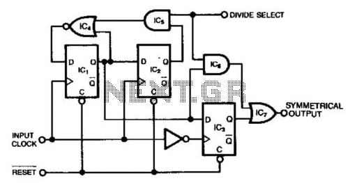
This circuit generates a symmetrical waveform by dividing the input frequency by either 2 or 3. The Divide Select input governs the division factor. When the Divide Select input is high, flip-flops IC1 and IC2, along with the associated...

The proposed remote control circuit can be utilized to control any electrical device within a range of 100 meters. This concept involves modifying an existing remote bell unit circuit, making the process straightforward. However, the construction aspect necessitates electronic...
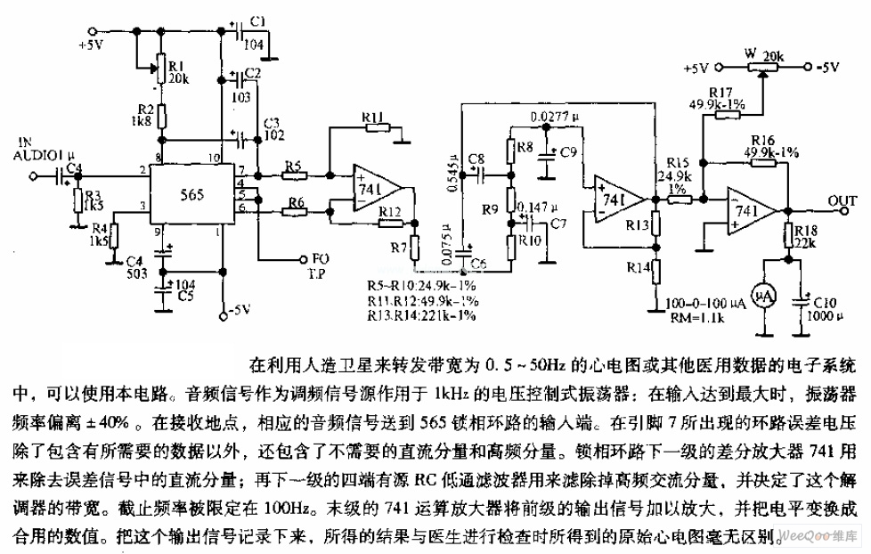
The circuit is designed for satellite transmission of ECG signals with a bandwidth range of 0.5 to 50 Hz, as well as other medical data within electronic systems. An audio signal serves as the FM signal source, which is...
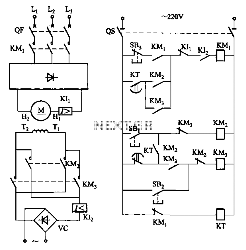
The circuit depicted in Figure 3-193 illustrates a separately excited DC motor. The brake circuit is not activated; therefore, positive reversals occur alternately using a delay action relay, ensuring that the motor reverses direction after coming to a stop. The...
This circuit is designed to maintain the liquid level between two fixed points. By transforming the K1 contacts off the case, it can perform filling or extraction operations in two modes. The load can be either an AC motor...