
Negative Resistance Oscillator Circuits

The circuit operates by leveraging the properties of negative resistance to facilitate oscillation, which is essential for generating sine waves. The arrangement of transistors Q1 and Q2 creates a robust current source, ensuring stable operation under varying load conditions. The role of the 300 kΩ resistor in conjunction with the LM394 matched transistor pair is critical for maintaining a consistent voltage-to-current conversion, which is necessary for the dynamic control of Q3's base current. As Q3's collector voltage increases, the base current is automatically adjusted, which is a fundamental aspect of the negative resistance behavior that allows for sustained oscillation.
The frequency of oscillation is primarily influenced by the LC network connected to the collector of Q3, where the inductance and capacitance values dictate the resonant frequency. This design choice is beneficial for applications requiring precise frequency stability and low distortion. The LF353 operational amplifier, known for its low noise and high bandwidth, serves to amplify the oscillating signal while also buffering it to prevent loading effects that could compromise the oscillation amplitude.
In addition, the inclusion of a zener diode in the power supply path ensures that voltage fluctuations do not affect the performance of the circuit. This is particularly important in environments where power supply variations are common. The LF353 configured as a unity gain follower further isolates the output from power supply variations, enhancing the circuit's reliability.
Overall, this negative resistance oscillator circuit is characterized by its ability to produce a clean sine wave output with minimal distortion, making it suitable for various applications in signal generation and waveform shaping. Its design emphasizes stability, rapid response, and low noise, which are crucial for high-performance electronic systems.This is a circuit of negative resistance circuits. All of the preceding circuits rely on RC time constants to achieve resonance. LC combinations can also be used and offer good frequency stability, high Q and fast starting. In the circuit, signal input is control and amp using op amp LF353. This is the figure of the circuit. In this circuit, a neg ative resistance configuration is used to generate the sine wave. The Q1-Q2 pair provides a 15 A current source. Q2s collector current sets Q3s peak collector current. The 300 k © resistor and the Q4-Q5 LM394 matched pair accomplish a voltage-to-current conversion that decreases Q3s base current when its collector voltage rises. This negative resistance characteristic permits oscillation. The frequency of operation is determined by the LC in the Q3-Q5 collector line. The LF353 FET amplifier provides gain and buffering. Power supply dependence is eliminated by the zener diode and the LF353 unity gain follower. This circuit starts quickly and distortion is inside 1. 5%. 🔗 External reference
Related Circuits
The RF design and construction of radio frequency oscillators. Radio frequency (RF) oscillators are essential components in various electronic systems, generating signals at specific frequencies used for communication, signal processing, and other applications. The design of RF oscillators involves several...

An oscillator is an electronic circuit that converts energy from a direct-current source into a periodically varying electric output. An oscillator is a fundamental component in various electronic systems, serving the purpose of generating oscillating signals, typically in the form...
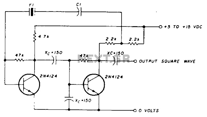
A transistor in series with capacitor C1 can be utilized to adjust the oscillator output frequency. The frequency may vary with changes in capacitance ranging from 20 pF to 0.01 µF, or as determined by the tuning capacitor. The...
The RF engineer occasionally needs to find an instrument that can reliably and quickly test a low-frequency quartz crystal unit. This equipment is often challenging to locate, leading engineers to consult electronic circuits handbooks for schematics that can perform...
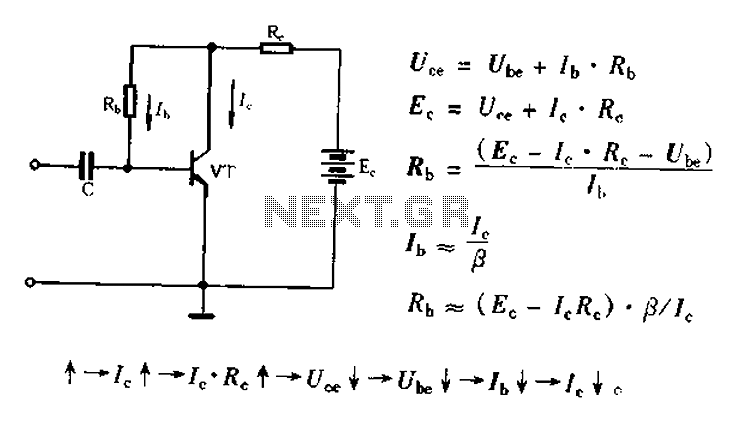
Bias voltage negative feedback circuit The bias voltage negative feedback circuit is a crucial component in various electronic applications, particularly in amplifiers and oscillators. This circuit is designed to stabilize the operating point of a transistor or operational amplifier by...

To prevent deep discharge that can damage or shorten the life of a rechargeable battery, it is essential to disconnect its load before the battery is completely discharged. The circuit protects against AC line disturbances by switching off the...