
Control circuit of automatic water

The automatic water control system incorporates a dual-level sensing mechanism to ensure efficient operation of the water supply infrastructure. The circuit utilizes float switches or pressure sensors placed at strategic locations within the water tower and reservoir to monitor the water levels continuously. These sensors are connected to a microcontroller or a relay-based control circuit that processes the input signals from the sensors.
When the water level in the reservoir or the water tower drops below a predetermined threshold, the sensors trigger the control circuit to activate the pump. The pump will continue to operate until the water levels in either the tower or the reservoir reach their respective upper limits. This configuration not only prevents the pump from running dry, which could cause damage, but also ensures that the water supply is maintained at optimal levels.
Additionally, the control circuit may include visual and audible indicators to alert operators of the system status, such as low water levels or pump operation. The use of timers and delays can be implemented to prevent rapid cycling of the pump, thereby enhancing the longevity of the equipment. Overall, this circuit design emphasizes reliability and efficiency, contributing to the effective management of water resources in the monitored area.In some places by the reservoir (or well) when the water level constraints to water towers, need to have with simultaneous monitoring of water towers and reservoirs (or well) of automatic water control system. That is when the water level in Sheung Shui being subject to control, but also at the same time by the water tank level control, in order to avoid water or reservoir water level is too low, the pump burned idling pumps cause accidents. Circuit design is based on: O pump starts automatically to meet two conditions, namely water tower and reservoir water level dropped to under water (ie water level above the lower bits); pump stops to draw with the proviso that the water level rise tower or supreme water reservoir water level dropped to the next level.
Related Circuits
The IC1 is a 555 timer IC connected for astable operation. The clock pulses are fed to the IC2 via the 10K resistor. The IC2 is a 10-stage counter; output 6 (pin 5) is connected to RESET (pin 15),...
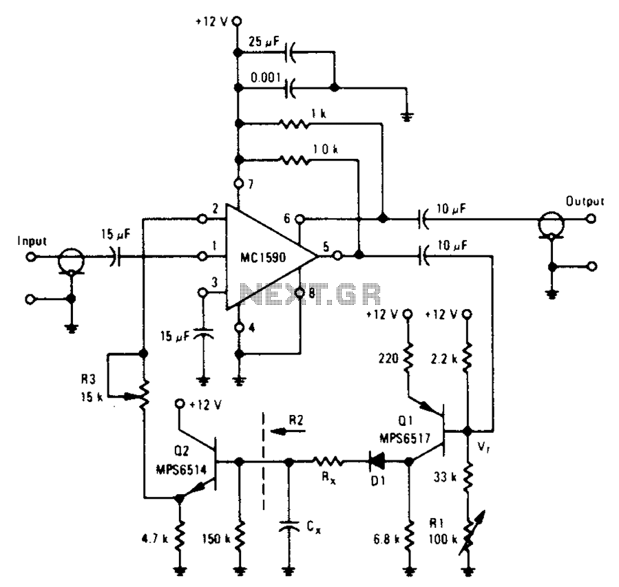
An amplifier designed to achieve a voltage gain of approximately 20, utilizing the MPS6517 PNP transistor in the emitter follower configuration. The RI controller allows for adjustment of the transistor's quiescent point. The output signal is activated only when...
The purpose of this circuit is to animate shop windows using a capacitive sensor positioned behind a postcard-like banner. The card is placed against the glass inside the shop window, allowing visitors to activate the relay by placing their...
The circuit diagram below illustrates a schematic designed to control the speed of a low-power induction motor, commonly found in fans. The schematic for controlling the speed of a low-power induction motor typically incorporates several key components that work together...

In a panic situation during the night when an intruder attempts to break into a house, this alarm system will assist by emitting a loud police siren to deter the intruder. The alarm system is designed to enhance home security...

Ideal for operating 3 to 24V DC existing on-circuit lamps. This circuit was designed to provide continuous light for lamps already wired into a circuit. The circuit is intended to facilitate the operation of existing DC lamps that are integrated...