
Digital Temperature Sensor Circuit using ADC0804 LM35 and LM317
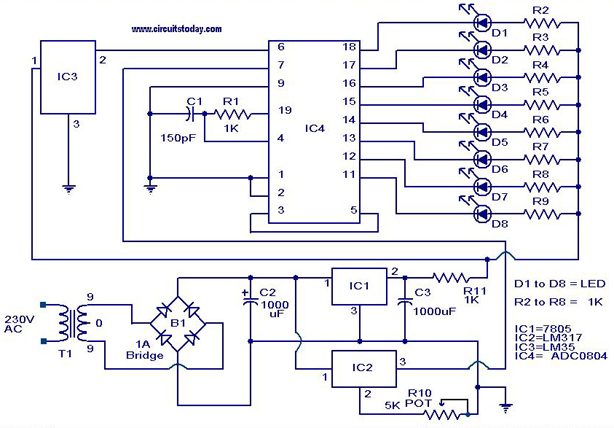
The digital temperature sensor circuit utilizes three primary integrated circuits (ICs): the ADC 0804, LM35, and LM317. The LM35 is a precision temperature sensor that outputs an analog voltage proportional to the temperature in degrees Celsius. This output is typically in the range of 0 to 1V for temperatures from 0°C to 100°C, making it suitable for various temperature monitoring applications.
The ADC 0804 is an 8-bit analog-to-digital converter that converts the analog voltage output from the LM35 into a digital signal. This conversion is essential for interfacing with microcontrollers or digital processing systems, allowing for digital display or further processing of temperature data. The ADC 0804 operates with a reference voltage, which must be carefully selected to ensure accurate conversion across the desired temperature range.
The LM317 is a voltage regulator that can be used in this circuit to provide a stable voltage supply to the LM35 and ADC 0804. It can adjust the output voltage based on the resistors used in its configuration, ensuring that the sensor and converter operate within their specified voltage ranges.
The circuit diagram typically includes connections between the LM35, ADC 0804, and LM317, along with additional components such as resistors and capacitors for signal conditioning and stability. Proper layout and grounding techniques should be employed to minimize noise and ensure accurate readings.
This digital temperature sensor circuit is versatile and can be adapted for various applications, including environmental monitoring, HVAC systems, and industrial automation, where precise temperature measurement is critical.A digital temperature sensor circuit is explained with circuit diagram.ICs ADC 0804,LM35 and LM317 are used in this digital circuit project.. 🔗 External reference
Related Circuits
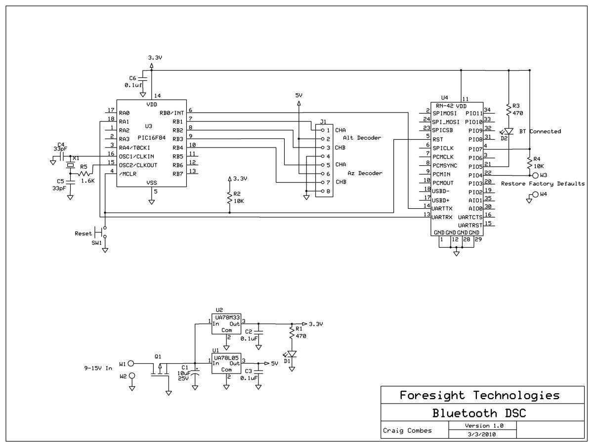
This variation of the Digital Setting Circles project was developed by Craig Combes, who shared his insights for others to replicate his version. Many users utilize Dave's serial DSC board along with a serial to Bluetooth adapter, which can...

The circuit consists of two main sections: a charger power supply and an LED driver. The charger power supply is designed using a 3-terminal adjustable regulator (IC1) LM317, while the LED driver is based on a BD140 transistor (T2)....

The Pyro Propeller Clock POV schematic is relatively straightforward. It consists of three primary components: the power supply utilizing a 7805 voltage regulator, the LED output control managed by a PIC18F252 microcontroller and a 74LS373 latch, and the 'home'...
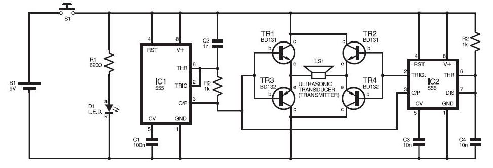
This ultrasonic sensor circuit consists of a set of ultrasonic receivers and transmitters that operate at the same frequency. When an object moves within the covered area, the circuit's balance is disturbed, triggering the alarm. The ultrasonic circuit is...
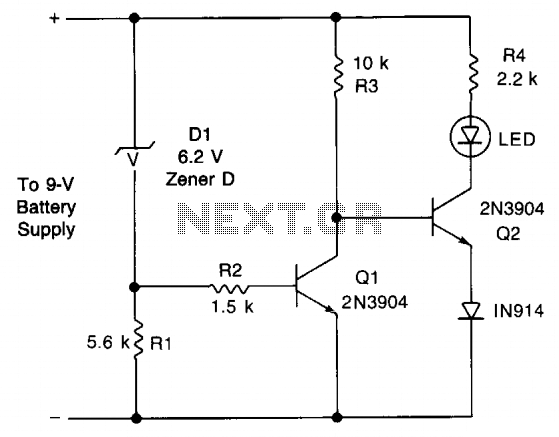
This circuit provides an early warning for battery discharge. A Zener diode (D1) is selected to indicate when the voltage falls below 9 V. If the supply voltage drops below 7 V, D1 will stop conducting, which will cause...
The dispenser (Aucma) temperature detection control circuit is designed to manage the temperature of the dispenser. It consists of two primary components: a heating control circuit and a fresh cabinet control circuit that provides power to an ozone generator....