
network wiring tester schematic circuit
The network wiring tester is designed to simplify the process of diagnosing wiring issues in network installations. The transmitter unit's circuitry is engineered to provide a reliable and adjustable signal output, allowing for flexibility in testing modes. The use of a Schmitt trigger in the multivibrator configuration enhances the stability of the output signal, ensuring that the LEDs light up in a clear and discernible sequence. The debounce circuit is crucial for preventing false triggering during manual mode operation, which can occur due to mechanical switch bounce.
The ULN2803 integrated circuit is a robust solution for driving the LEDs, as it can handle higher current loads without risking damage to the LEDs or the circuit itself. This is particularly important in scenarios where shorts or other wiring faults could lead to excessive current draw. The design also incorporates safety measures to protect the circuit from potential damage while allowing for effective testing of the wiring.
The receiver unit's simplicity, with its eight LEDs and current-limiting resistors, allows for straightforward visual feedback during testing. The requirement for a common connection underscores the importance of grounding in network installations, ensuring that the testing process provides accurate results. The flexibility in power supply options, including the use of a 9V battery, adds to the tester's versatility, making it suitable for various testing environments.
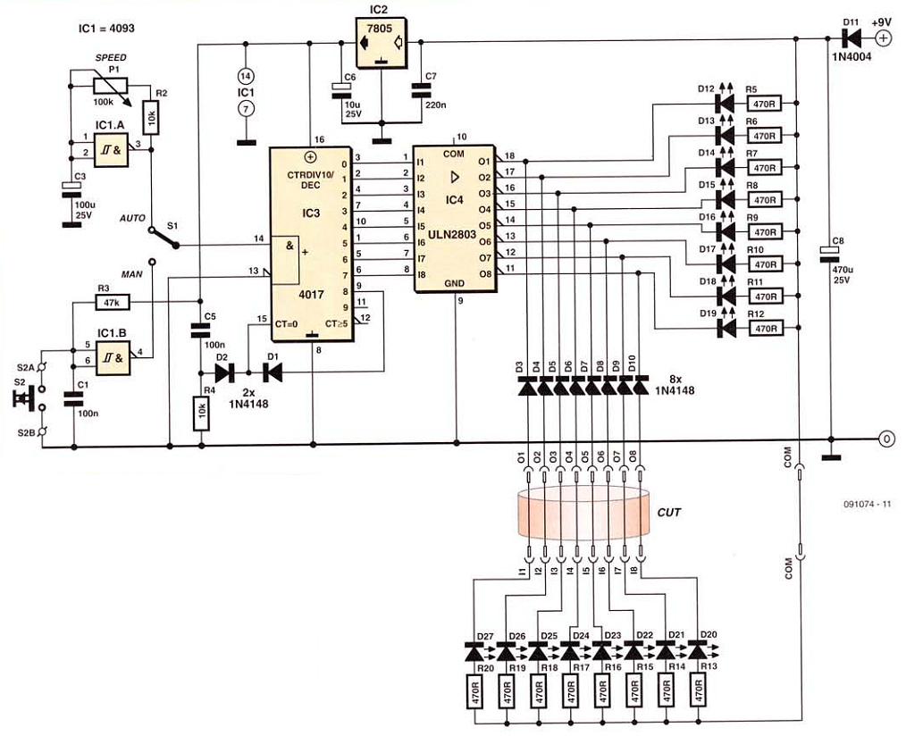
In summary, this network wiring tester is an essential tool for professionals in the field of electronics and networking, providing a clear and efficient means of identifying wiring issues through a well-designed LED signaling system.This network wiring tester comprises two elements, a transmitter unit, powered and fitted at the network start point, and a receiver unit, passive, which can be moved around from socket to socket. Each of these units carries eight LEDS, identically labelled 1 to 8. By operating a push-button in manual mode, or using a clock in automatic, the eight LEDs light up in sequence
on the transmitter unit and obviously they should do the same on the receiver unit. In this way, just by watching the LED lighting cycle on the receiver unit, you can immediately spot any crossed wires, as well as any open circuits (the relevant LED never lights up) or shorts (two or more LEDs light at the same time). The transmitter unit circuit is simple` The Schmitt-input NAND gate lCl. A is wired as a multi-vibrator, whose speed can be adjusted using Pl, while lCl. B is wired as a simple debounce circuit for button 52, used in manual mode. Switch 51 lets you apply the output of one or the other of these to the input of lC3 ² a decade counter lC, which here we force to count up to eight by connecting its Q8 output back to its reset input.
Its out Puts are not capable of driving LEDs, especially over wiring that be dangerous` for them (a short, for example), so a ULN2803 is used to drive the outputs. This integrated network of eight Darlington transistors, each capable of switching up to 500 mA, drives the eight LED5 fitted to the transmitter unit (D12-D19) and feeds its signals to the socket comprising contacts 01-08, to which the wiring to be tested must be connected.
At the other end of the cable` via the socket comprising contacts l1-18, is the receiver unit which contains just eight LEDs (D20-D27) and their current limiting resistors. For the latter to work, there obviously needs to be a common connection between transmitter and receiver.
In the case of screened network wiring, the screen can be used for this purpose. Another solution consists of using the earth wire of the electrical installation to fulfilthe same function. But if neither of these solutions is feasible, then you`ll have to resign your self to running a flying lead for this purpose.
The transmitter unit power supply is obtained from a plugtop` adapter supplying around 9V at around 10 mA or so. The supply to lCl and lC3 is regulated at 5 V, even though it`s not strictly necessary. For occasional short use, a 9 V battery could be used. lf the project is intended solely for testing network wiring, 01-08 and l1-18 will be in the form of RJ45 sockets and COM will be connected to their screening contact.
Take care to stick to the same numbering for the LEDs on the transmitter and receiver units, and if the project is going to be used in automatic mode, that the LEDs are in the correct order. 🔗 External reference
Related Circuits
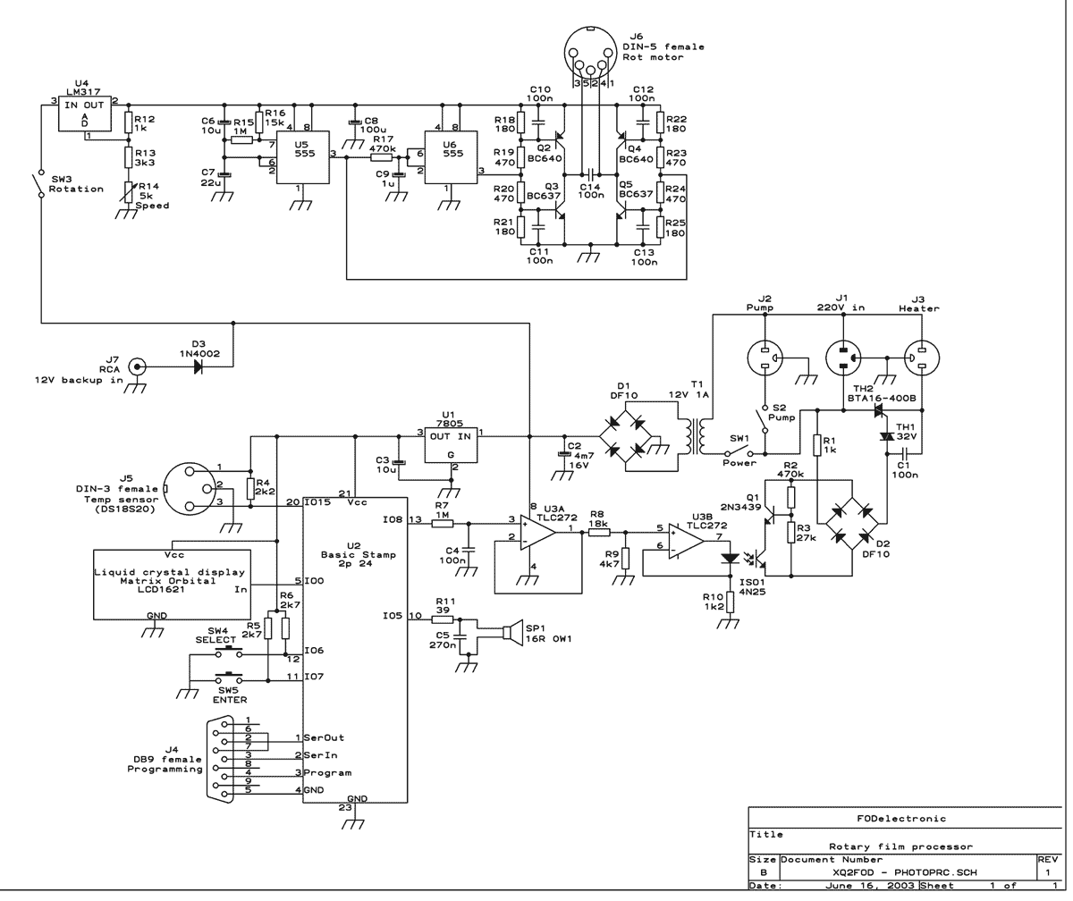
This machine essentially does three things: It controls the process temperature, provides constant agitation of the chemical baths, and performs the timing. The operator must pour in and out the liquids by hand. The heart of the circuit is...
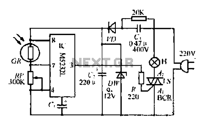
The DW L11 capacitor steps down voltage into the Jenru half crossing according to Yin electrical specifications. After receiving power at the bin CI SH output terminal, it regulates the voltage to liVI/r j, ensuring a right cut in...
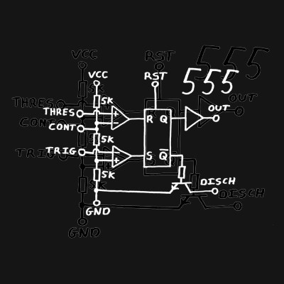
Classic 555 timer chip schematic circuit t-shirt by EEVblog picture on VisualizeUs - bookmark pictures and videos that inspire you. Social bookmarking of pictures and videos. Find your pictures and videos. The 555 timer IC is a versatile and widely...
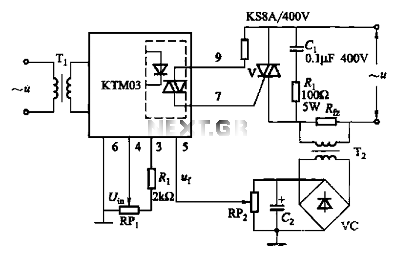
An adjustment potentiometer (RP) is utilized to set the voltage across the load resistor (Rfz) to a predetermined value. The real-time closed-loop control is achieved through the potentiometer (RPz). Open-loop control is functional as long as the feedback voltage...
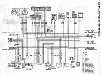
The following circuit illustrates the electrical circuit diagrams for the Toyota Supra. The diagrams indicate the point at which the power source is received. The electrical circuit diagrams for the Toyota Supra provide a comprehensive overview of the vehicle's electrical...
This circuit emits an intermittent beep or flashes an LED when the water level in a container reaches a predetermined height. It is designed to be mounted on top of the container, such as a plastic tank, using two...
Warning: include(partials/cookie-banner.php): Failed to open stream: Permission denied in /var/www/html/nextgr/view-circuit.php on line 713
Warning: include(): Failed opening 'partials/cookie-banner.php' for inclusion (include_path='.:/usr/share/php') in /var/www/html/nextgr/view-circuit.php on line 713