
KTM03 type of circuit for controlling the triac
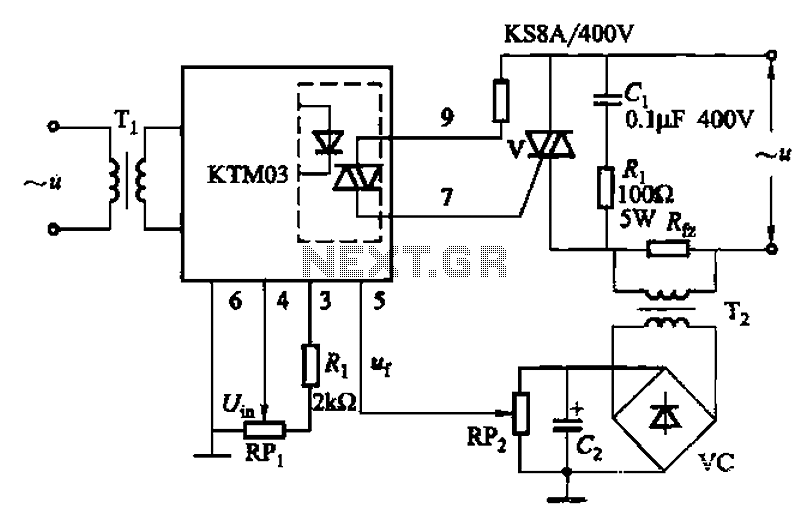
The circuit employs an adjustment potentiometer (RP) to facilitate the setting of the output voltage across the load resistor (Rfz). This configuration is essential for achieving precise control over the voltage supplied to the load, which is critical in various applications such as power supplies or signal conditioning circuits.
The closed-loop control system, enabled by the potentiometer (RPz), allows for real-time adjustments based on feedback. The feedback voltage (Uf) plays a crucial role in maintaining the desired output voltage. When the feedback voltage is grounded, the system operates in an open-loop mode, meaning that it does not utilize feedback to adjust the output. This mode can be beneficial in certain scenarios where the system's behavior is predictable and does not require constant adjustment.
In such a circuit, the potentiometer (RP) is typically connected in a voltage divider configuration. By rotating the potentiometer's knob, the resistance changes, thereby altering the voltage drop across it. This change in voltage directly influences the voltage across the load resistor (Rfz), allowing for fine-tuning of the output as needed.
The design must ensure that the potentiometer can handle the power levels involved without overheating or degrading over time. Additionally, considerations regarding the tolerance of the components, the range of adjustment required, and the stability of the feedback loop are essential for optimal performance.
In summary, the integration of an adjustment potentiometer in the circuit enables precise voltage control across the load, with the potential for both closed-loop and open-loop operation depending on the feedback configuration. This versatility makes it a valuable component in various electronic applications.Adjustment potentiometer RP, the voltage on the load Rfz Uh set value. By RPz real now closed loop control. Open-loop control works, as long as the feedback voltage Uf ground c an be.
Related Circuits
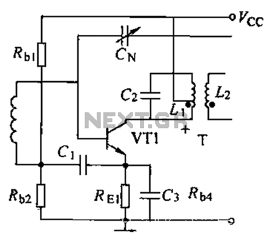
A common intermediate frequency amplifier circuit is presented, along with its components and parameters. The reference values for the components are as follows: 1) Transistors: VT1 to 3DG19, Vcc = 6V. 2) Resistance values: R1 = 50 kΩ, R2...
Police siren circuit diagram. This circuit produces a sound similar to a police siren. It utilizes two 555 timer ICs. The police siren circuit typically employs two 555 timer integrated circuits (ICs) configured in astable mode to generate a square...
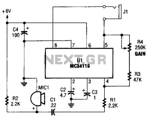
The first amplifier circuit is a bird phone. In this circuit, the electret microphone (MIC1) is mounted in the neck of a large plastic funnel. The amplifier, built around an MC34119, is then placed outside of the funnel with...
The TDA8444 is a digital-to-analog (D/A) converter integrated circuit (IC) produced by Philips. It is designed to convert digital signals into analog signals. The TDA8444 IC utilizes a 16-pin dual in-line package, with specific pin functions and data outlined...
S1 and S2 are normally open, push-to-close, momentary switches. The diodes, which can be either red or green, serve solely to indicate the direction of operation. The TIP31 transistors may need to be adjusted based on the specifications of...
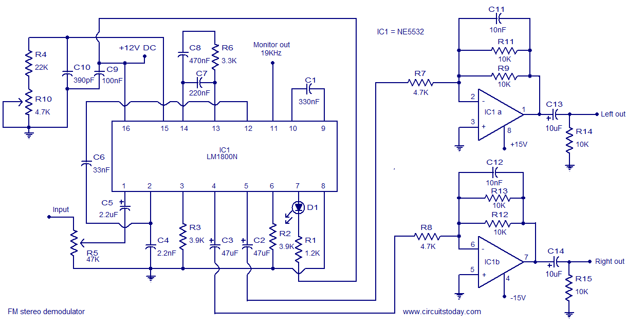
The following circuit illustrates the LM1800 IC Integrated FM Stereo Demodulator Circuit. Features include excellent sound quality and high-quality FM stereo. The LM1800 Integrated Circuit (IC) serves as a highly effective FM stereo demodulator, designed to deliver superior audio performance...