
New Phono amp

The attached schematic represents a recent design that integrates various electronic components to achieve a specific functionality. The circuit may include a power supply section, signal processing units, and output stages, depending on the intended application.
In the power supply section, a voltage regulator may be implemented to ensure a stable output voltage, which is crucial for the reliable operation of the circuit. This section typically includes input capacitors to filter out noise and output capacitors to stabilize the voltage under load conditions.
The signal processing units could consist of operational amplifiers, filters, or microcontrollers, depending on the complexity of the design. Operational amplifiers might be configured for amplification, filtering, or signal conditioning, while digital components could be employed for more advanced processing tasks, such as data acquisition or control algorithms.
Output stages are essential for interfacing with external devices or systems. This could include transistor drivers for controlling motors or LEDs, or digital-to-analog converters if the circuit is designed for audio or analog signal output.
Each component in the schematic should be clearly labeled with its value and rating, including resistors, capacitors, and integrated circuits. Additionally, the connections between components must be accurately represented to ensure proper functionality when the circuit is assembled.
This comprehensive approach to schematic design emphasizes clarity and precision, facilitating easier troubleshooting and modification in future iterations of the circuit.Very interesting points Chris and Thoersten, but I`d like to make a little step back. So, talking about my lastest design, this schematic attached.. 🔗 External reference
Related Circuits
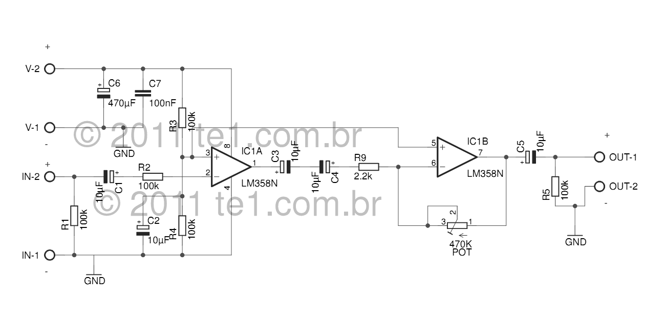
The LM358 series consists of two independent, high-gain, internally frequency-compensated operational amplifiers designed specifically to operate from a single power supply over a wide range of voltages. Operation from split power supplies is also possible, and the low power...
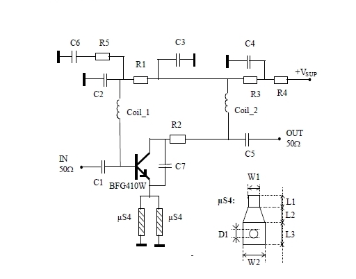
This 900 MHz amplifier circuit is constructed using the BFG480W transistor, which exhibits excellent linearity performance. As a result, the BFG480W is highly suitable for low-noise amplifiers (LNAs) that require high linearity. The 900 MHz amplifier circuit utilizing the BFG480W...
60W Bass Amplifier. It features low-cut and bass controls. The output power is 40W on 8 Ohm loads and 60W on 4 Ohm loads. An amplifier circuit diagram is provided. The 60W bass amplifier is designed to deliver robust audio...
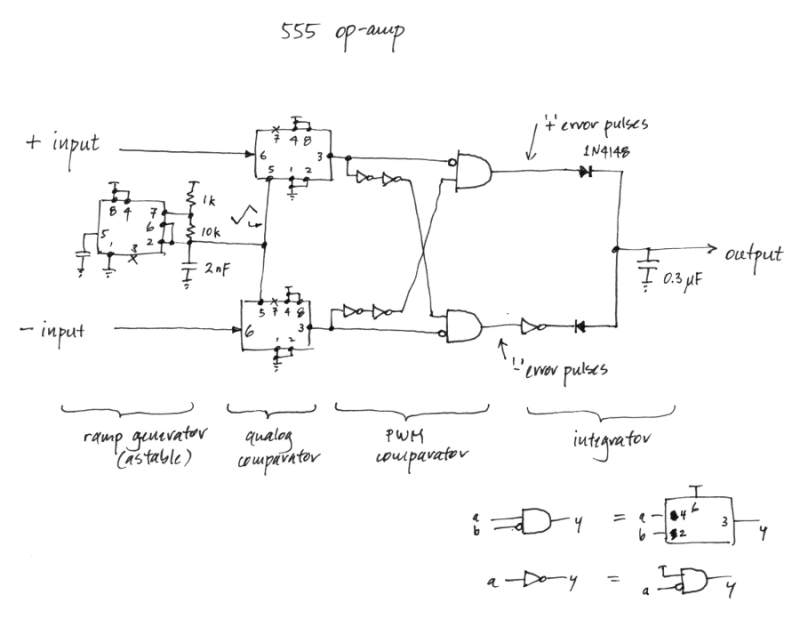
Is it feasible to create an operational amplifier using only 555 timer chips and passive components? While this may not be a practical inquiry, given the availability of low-cost and efficient op-amps, it does have some aesthetic interest. In...
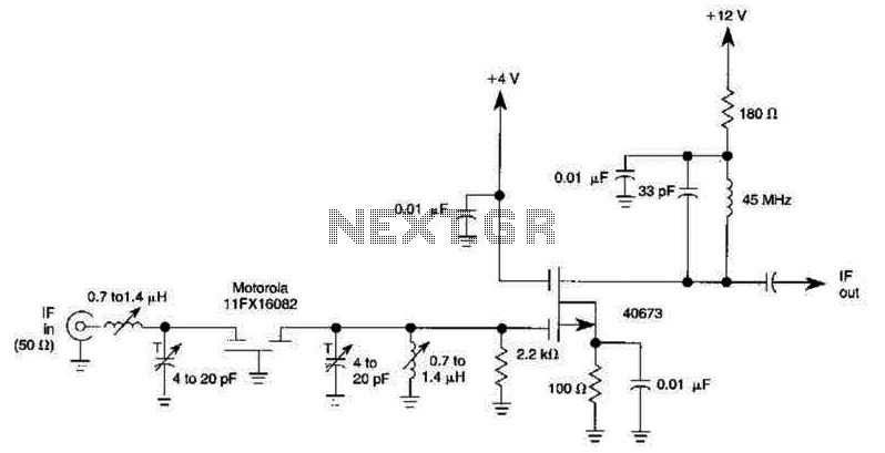
A 40673 dual-gate MOSFET is matched to a crystal filter operating at 45 MHz. The filter impedance is approximately 2 kΩ. The +4 V source can be adjusted to control the gain, ranging from +4 V to -4 V. The...
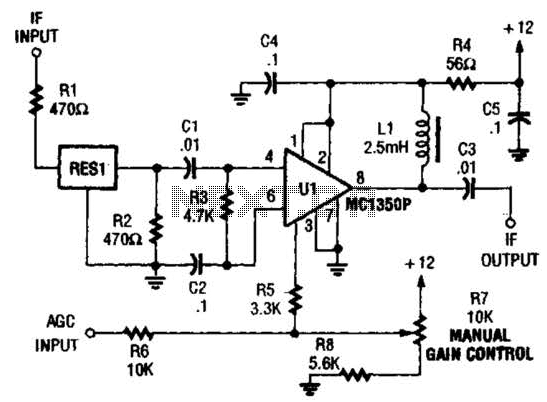
The ZN416E can be configured as a simple 455-kHz IF amplifier. In this case, the circuit's center and bandwidth are set by RES1 (a Murata CSB455E ceramic resonator). The ZN416E is a versatile integrated circuit designed for use as a...