
900 MHz Radio Amplifier Circuit
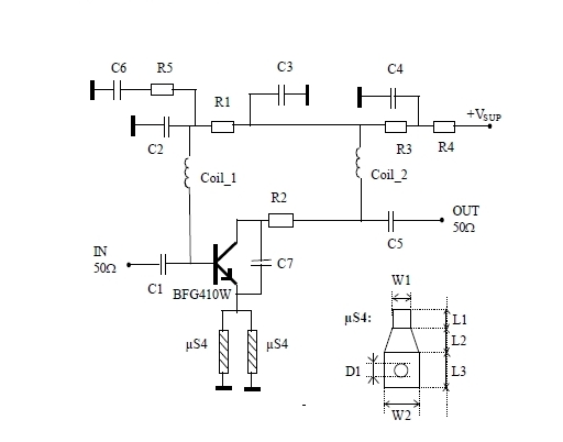
The 900 MHz amplifier circuit utilizing the BFG480W transistor is designed to operate efficiently within the specified frequency range, making it ideal for applications in communication systems where signal integrity is paramount. The BFG480W is a high-frequency NPN transistor known for its low noise figure and high gain, which are essential characteristics for low-noise amplification.
In this circuit, the BFG480W is typically configured in a common-emitter configuration to maximize voltage gain while maintaining stability. The input stage may include impedance matching networks to ensure optimal power transfer from the source to the amplifier. This can involve the use of inductors and capacitors to create a tuned circuit that resonates at 900 MHz.
Biasing is a critical aspect of the design to ensure the transistor operates in the linear region. Resistors are used to set the appropriate DC operating point, taking into account the supply voltage and the desired quiescent current. Capacitors may be employed for AC coupling at the input and output to block DC components while allowing AC signals to pass through.
The amplifier's output stage can also include a matching network to minimize reflections and maximize power transfer to the load. This is particularly important in RF applications, where mismatches can lead to signal degradation and reduced performance.
Overall, the design of a 900 MHz amplifier circuit using the BFG480W requires careful consideration of component values, layout, and thermal management to ensure reliable operation and optimal performance in various applications, including wireless communication and broadcasting.This 900 MHz Amplifier Circuit is built with BFG480W which has a good linearity performance. Therefore the BFG480W is well suited for LNAs with high linear.. 🔗 External reference
Related Circuits
Here is an inexpensive electronic circuit that can be built to place in a Jack-o'-lantern. It provides power to drive a few LEDs at night and automatically turns them off during the daytime. This is a simple and automatic...
Various values of D3 can be utilized to achieve different output voltages ranging from approximately 0.6V to around 30V. It is important to note that at elevated voltages, the circuit's performance may diminish, potentially resulting in lower current output....
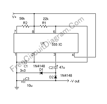
If a negative supply is required for an operational amplifier or if a negative bias voltage is needed while operating from a single supply voltage, such as in battery applications. To generate a negative supply voltage from a single positive...
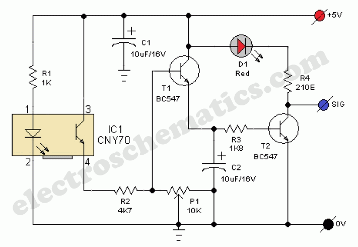
This presence detector or proximity sensor circuit responds to the presence of any conductive object, including humans. The sensitivity can be adjusted with potentiometer P1, which is positioned at a considerable distance from the rest of the circuit. This...
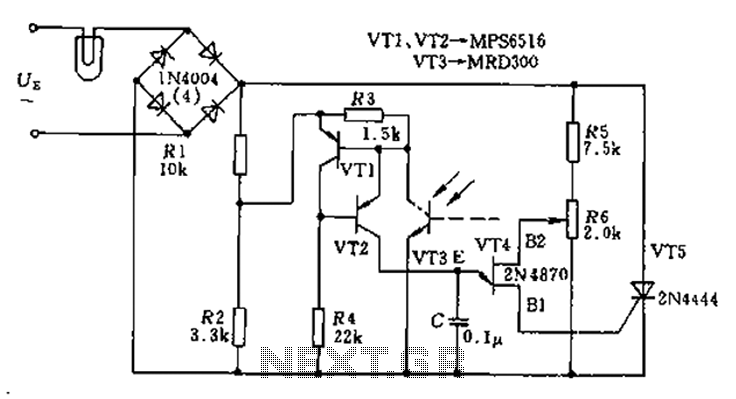
The circuit utilizes a thyristor-based AC automatic voltage regulator to stabilize the brightness of lamp L. A diagonal line connects the thyristor to the T5 bridge. The trigger pulse for the thyristor is generated by a single-junction transistor, VT4....
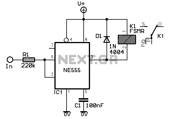
The camera has been wired with external shutter leads, and a method is needed to trigger them. These leads must be connected together via a relay at regular intervals, approximately every 2 seconds, starting from launch. A 555 timer...