
60W Bass Amplifier
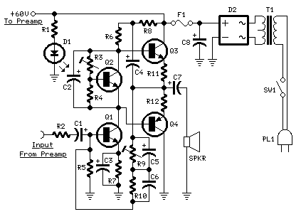
The 60W bass amplifier is designed to deliver robust audio performance tailored for low-frequency sounds, making it ideal for bass instruments and music genres that emphasize bass. The amplifier incorporates low-cut and bass controls, allowing users to adjust the frequency response to suit their preferences and the acoustics of the environment.
The output power specifications indicate that the amplifier can deliver 40W when connected to an 8 Ohm load, which is typical for many speaker configurations. When connected to a 4 Ohm load, the amplifier can produce a maximum output of 60W, providing increased power for more demanding applications or larger speaker setups.
The circuit design of the amplifier is critical to its performance. It typically consists of a preamplifier stage, which processes the audio signal before it is amplified, and a power amplifier stage, which drives the speakers. The low-cut control is likely implemented using a high-pass filter, which removes unwanted low-frequency signals that may muddy the sound. The bass control may employ a variable gain stage or a shelving filter to enhance low-frequency output selectively.
In terms of component selection, high-quality capacitors and resistors are essential for maintaining signal integrity and minimizing distortion. The use of a robust power supply is also crucial, as it must provide sufficient current to handle the dynamic demands of bass frequencies without introducing noise or sagging voltage.
The amplifier's schematic diagram would typically include the layout of these components, interconnections, and any additional features such as protection circuits to prevent damage from overload or short circuits. Overall, the 60W bass amplifier is engineered to deliver powerful, clear sound reproduction, making it suitable for both live performances and studio applications.60W Bass Amplifier. Low-cut and Bass controls Output power: 40W on 8 Ohm and 60W on 4 Ohm loads Amplifier circuit diagram: Amplifier. 🔗 External reference
Related Circuits
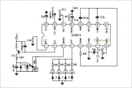
The SA9618A is designed for ALPC and signal conversion between a CD optical pickup and a decoding chip. This integrated circuit (IC) features an interconnection for a general CD optical pickup photodiode bias voltage VREF generation circuit, an RF...
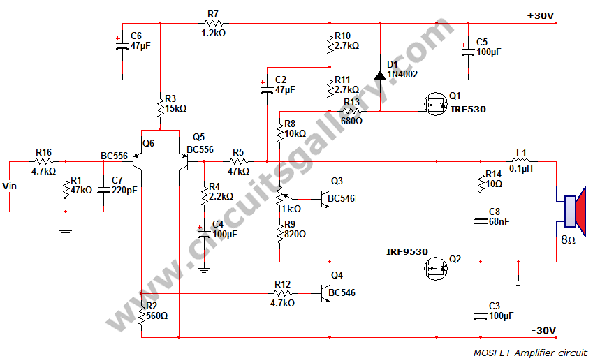
This is a MOSFET transistor-based power amplifier circuit that operates within a voltage range of +35V to -35V. The input voltage is pre-filtered and pre-amplified before being applied to the MOSFET switch. The pre-audio amplifier consists of a differential...
The converter depicted in Figure 1 utilizes a component from the PeakSwitch family (U1, a PKS606YN) to operate a 36 W motor, capable of handling startup and load transition peaks of up to 72 W. The motor speed can...
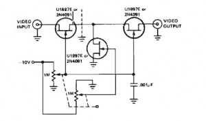
A variable gain amplifier controlled by voltage, functioning as a video amplifier. It utilizes three Field Effect Transistors (FETs) of type U1897E, which can be substituted with 2N4091. The described variable gain amplifier is designed to adjust its gain based...

This is a simple headphone amplifier circuit designed to drive headphones when a music player lacks sufficient power. The circuit is straightforward and utilizes only three transistors. The first transistor, Q1 (BC 239), along with its associated components, functions...
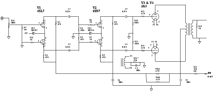
The input stage is comprised of both halves of a 6SL7 octal dual hi-mu triode in a differential amp configuration with a 1mA constant current cathode load. Field-effect (constant-current) diodes are used for simplicity. The differential amp approach was...