
Ni-Cad battery charger

This circuit utilizes a zapper to eliminate shorts in nickel-cadmium (Ni-Cad) batteries. The design incorporates a silicon-controlled rectifier (SCR) to manage the discharge current effectively. The SCR serves as a switch that can handle high currents, ensuring that the heavy discharge does not affect the integrity of the switch contacts.
In the schematic, the zapper is connected to the battery terminals, allowing for a controlled discharge to occur when a short is detected. When activated, the SCR allows current to flow through the short circuit, generating heat that effectively "burns off" the short. This process requires careful calibration to ensure that the current level is sufficient to clear the short without causing damage to the battery or the zapper circuitry.
The circuit may also include additional components such as resistors and capacitors to stabilize the operation and provide feedback to the SCR. The use of a diode may also be included to prevent reverse current flow, which could potentially harm the circuit. Proper heat dissipation mechanisms should be considered to ensure the SCR does not overheat during operation.
Overall, this circuit provides a practical solution for addressing shorts in Ni-Cad batteries, enhancing their longevity and reliability in various applications. Following the provided diagram will ensure accurate assembly and functionality of the zapper circuit.The short in a Ni-Cad battery can be "burned off" with this zapper. Use of the SCR keeps heavy discharge current from damaging switch contacts. follow the diagram.
Related Circuits
The ASUS Eee is an ultra-portable notebook designed for tech enthusiasts, offering essential features without unnecessary extras. It boasts excellent build quality and is competitively priced. In New Zealand, it can be purchased exclusively from DSE, making it cost-effective...
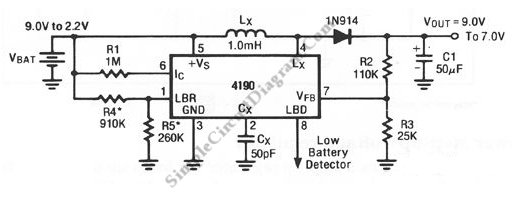
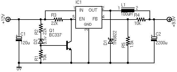
A standard 9V battery is considered depleted when its voltage drops below 7 volts. This switching regulator can extend the lifetime of a 9V battery. The circuit utilizes a switching regulator to optimize the energy usage of a standard 9V battery,...
Most 24V power systems in trucks, 4WDs, RVs, boats, and similar applications utilize two series-connected 12V lead-acid batteries. The charging system is capable of maintaining the total voltage of the individual batteries. If one battery is experiencing failure, this...
The ideas presented here explore various methods for controlling and monitoring the charging of lead-acid storage batteries. To ensure that the benefits of digital technology impact education in developing regions, reliable access during school hours is essential. The O-1.75...
The purpose of a DC power supply is to deliver the necessary level of DC power to a load by utilizing an AC supply at the input. Various applications demand different specifications; however, contemporary DC power supplies often ensure...
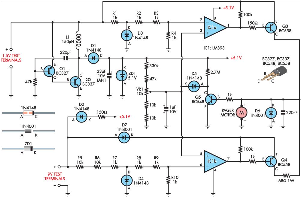
Many blind and deaf-blind individuals utilize portable electronic devices to assist in their daily activities; however, testing the batteries used in such equipment can be challenging. While talking voltmeters are available for the blind, there is no commercially available...