
Nicad Battery Charger
The charger circuit described operates by employing a BD140 transistor configured as a constant current source, which is essential for safely charging rechargeable batteries. The use of two 1N4148 diodes in series creates a stable voltage drop that is necessary for biasing the transistor's base. This arrangement ensures that the transistor operates within its linear region, allowing it to maintain a steady output current, which is critical in battery charging applications.
When the switch is closed, the circuit can deliver two different charging currents: 15mA for lower capacity batteries and 45mA for higher capacity batteries. This feature provides flexibility in charging various types of batteries, making the charger versatile for both 1.5V and 9V applications. The choice of a transformer with a 12V AC secondary rating at 0.5A is appropriate, as it provides sufficient power for the charging process while maintaining safety and efficiency.
The primary side of the transformer must be selected based on the regional voltage supply, either 220/240 volts for European systems or 120 volts AC for North American systems. This ensures that the transformer operates correctly within its specified voltage range, preventing overheating or failure.
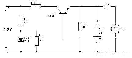
Safety precautions are paramount when working with this circuit. The use of a voltmeter to check polarity before connecting the battery is crucial, as incorrect connections can lead to catastrophic failures, such as battery explosions. Nickel-cadmium batteries, in particular, are sensitive to improper handling, and caution should always be exercised during operation. By following these guidelines and understanding the circuit's functionality, users can effectively and safely charge their rechargeable batteries.This simple charger uses a single transistor as a constant current source. The voltage across the pair of 1N4148 diodes biases the base of the BD140 medium power transistor. The base - emitter voltage of the transistor and the forward voltage drop across the diodes are relatively stable. The charging current is approximately 15mA or 45mA with the switch closed. This suits most 1. 5V and 9V rechargeable batteries. The transformer should have a secondary rating of 12V ac at 0. 5amp, the primary should be 220/240volts for Europe or 120volts ac for North America. WARNING: Take care with this circuit. Use a voltmeter to observe correct polarity. Nicads can explode if short circuited or connected with the wrong polarity. 🔗 External reference
Related Circuits
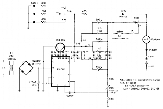
The rectified and filtered voltage from the 24 Vac transformer is applied to the LM723 voltage regulator and the NPN pass transistor configured for constant current supply. A 470-ohm resistor limits trickle current until the momentary pushbutton (S2) is...
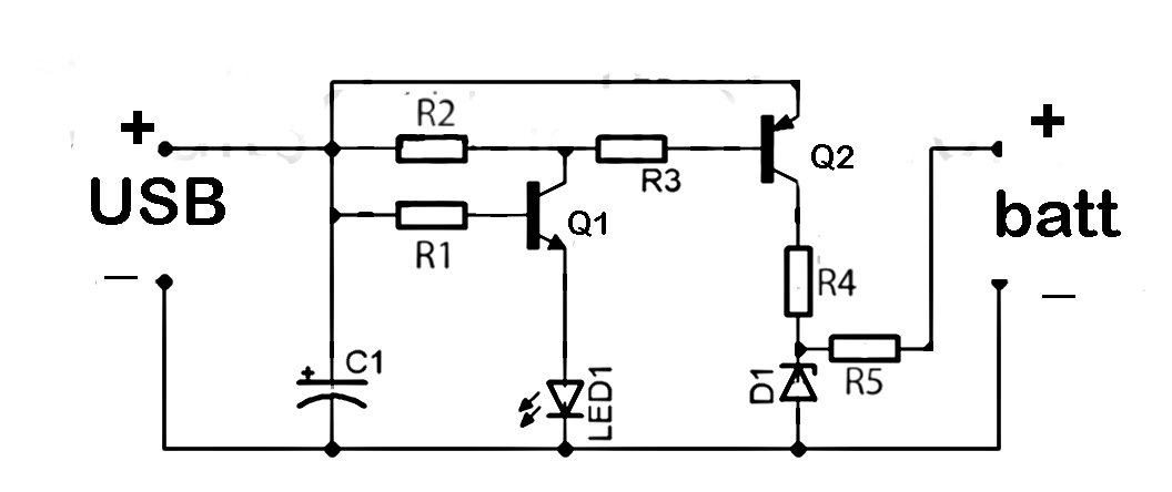
This document discusses the series used in USB connections for charging batteries. The output voltage ranges from 4.7 volts to 5 volts DC, which is suitable for charging mobile phones and other battery types. The circuit described enhances the...
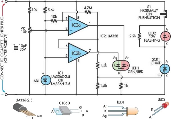
A car battery deteriorates in use, and its life seldom exceeds four years. When new, its voltage may drop to only 2V while cranking the engine. A car battery, typically a lead-acid type, is essential for providing the necessary electrical...
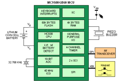
Battery-powered devices, such as electric toothbrushes, shavers, cell phones, PDAs, MP3 players, and remote controls, are integral to daily life. Consequently, power management has become a critical consideration for embedded designers. Microcontrollers (MCUs) provide various methods for managing power...
The Accu charger circuit is straightforward and simple to construct, requiring no more than ten components. In addition to its ease of assembly, this charger circuit is also cost-effective and highly efficient. The circuit requires a power supply from...
The schematic diagram originates from a circuit designed for a Car Lamp Charger power supply. The diagram illustrates a Car Lamp Charger circuit, which features a unique characteristic: the battery will not recharge. This circuit is integrated into a...
Warning: include(partials/cookie-banner.php): Failed to open stream: Permission denied in /var/www/html/nextgr/view-circuit.php on line 713
Warning: include(): Failed opening 'partials/cookie-banner.php' for inclusion (include_path='.:/usr/share/php') in /var/www/html/nextgr/view-circuit.php on line 713