
Rapid battery charger
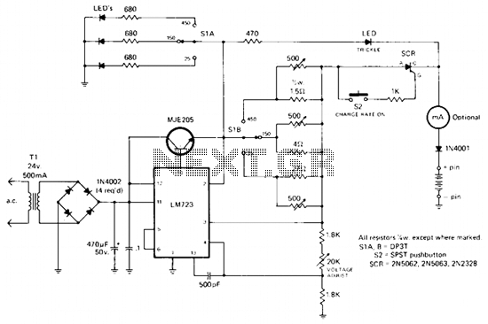
The circuit utilizes an LM723 voltage regulator, which is designed to provide a stable output voltage. This regulator is particularly effective in applications requiring constant current, as it can be paired with an NPN transistor to enhance current handling capabilities. The NPN transistor acts as a pass element, allowing for higher current output while the LM723 maintains voltage regulation.
The 470-ohm resistor plays a critical role in controlling the trickle charge to the battery, ensuring that it receives a minimal current until the system is actively engaged. The momentary pushbutton switch (S2) serves as an activation mechanism; when pressed, it triggers the silicon-controlled rectifier (SCR). The SCR is a semiconductor device that allows current to flow in one direction when triggered, enabling the charging process to commence.
The charging current is limited by a resistor network that has been carefully calculated to prevent overcharging, thus protecting the battery from potential damage. This network ensures that the battery receives a safe and controlled amount of current during the charging phase.
Additionally, the thermal cutout circuit within the battery pack is a crucial safety feature. It monitors the temperature of the battery and disconnects the charging circuit if the temperature exceeds a predetermined threshold. This action effectively turns off the SCR, ceasing current flow and preventing overheating, thereby enhancing the overall safety and reliability of the charging system.
In summary, this circuit design integrates several components to create a robust and safe charging solution for battery systems, emphasizing stability, current control, and thermal protection.Rectified and filtered voltage from the 24 Vac transformer is applied to the LM723 voltage regulator and the npn pass transistor set up for constant current supply. The 470 ohm resistor limits trickle current until the momentary pushbutton (S2) is depressed, the SCR turns on and current flows through the previously determined resistor network limiting the charging current.
The SCR will turn off when the thermal cutout circuit inside the battery pack opens up. 🔗 External reference
Related Circuits
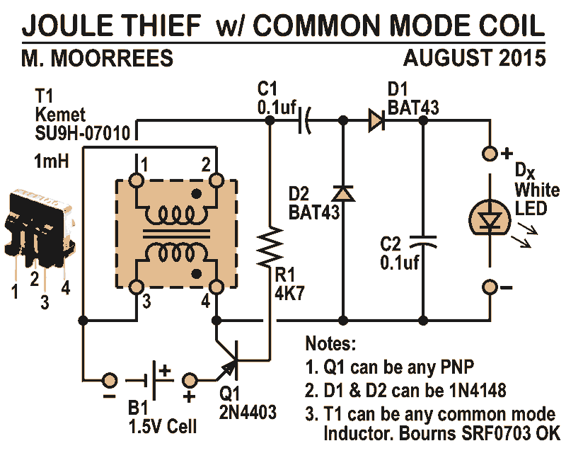
Like all joule thieves, this circuit boosts the voltage from a single 1.5V dry cell battery high enough to illuminate ultrabright GaN blue, green, or white LEDs. Instead of requiring a custom coil, it utilizes an off-the-shelf standard Kemet...
A charger is essential for charging a 12 Volt battery from a 12 Volt source due to the typical voltage variation between 11 Volt and 15 Volt. A battery requires a controlled charge current and voltage, which cannot be...

The concept involved removing the center page from a magazine and cutting it into four pieces to create a card suitable for a filing system. The front side of each card provided connections to the integrated circuit (IC), while...
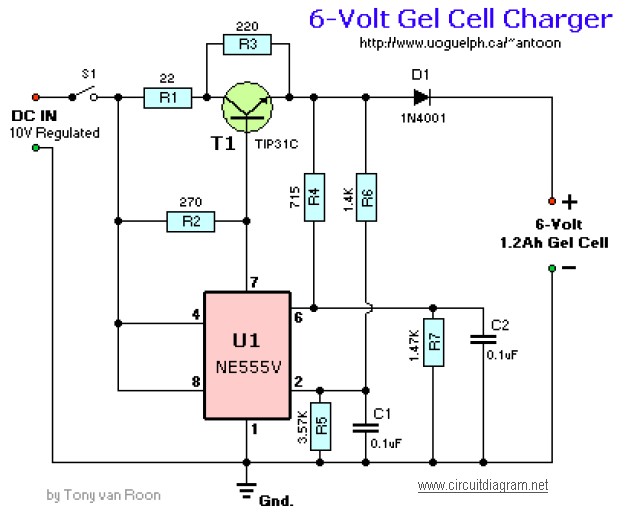
This circuit requires an adapted 10V DC power supply capable of delivering 2 Amps. It initiates the charging process at 240mA and automatically switches to a float charge (trickle charge) of 12mA when fully charged. The capacitors used should...
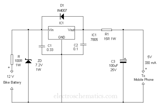
This is a simple and easy method to extract current from a motorcycle battery to charge a mobile phone. Most mobile phone battery packs consist of three 1.2 V cells. To effectively tap current from a motorcycle battery for mobile...
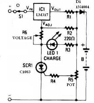
This schematic circuit for a battery charger consists of very few components but operates effectively. When power is applied to the circuit, SCR1 remains off, preventing any bias current from flowing to ground. The LM317 voltage regulator is connected...