
NiCd Battery Charger
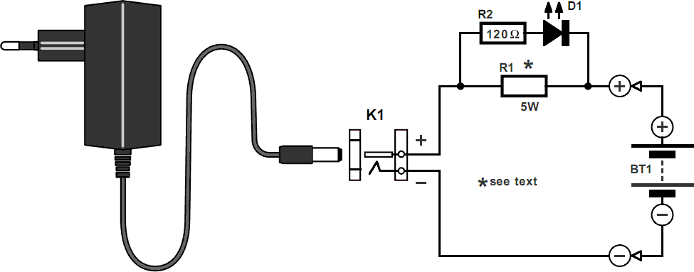
The charger circuit is designed for efficient battery charging, utilizing a simple yet effective configuration. The mains adapter provides the necessary input voltage, which is converted into a suitable output for charging the battery. The charging process is indicated by the LED, which illuminates when the charging current is active, offering a visual confirmation of the charging status.
Resistor R1 plays a critical role in determining the charging current; it is essential to select R1 based on the specific battery capacity to ensure optimal charging. The calculation of R1 is crucial, as it directly impacts both the charging current and the voltage drop required for LED operation. The adjustment of the mains adapter output to 1.17 times the nominal battery voltage plus the additional voltage drop across R1 ensures that the battery receives the correct voltage for charging.
The second resistor in the circuit, which is not explicitly detailed, may serve as a current limiting or voltage dividing element, depending on the specific design requirements. The power rating of R1 is particularly important, as it must withstand the heat generated during operation without failing. A 5 W rating is specified to provide a safety margin, ensuring that R1 operates within safe thermal limits.
In practical applications, the charger circuit can be adapted for various battery types and capacities by recalculating R1 and possibly adjusting other components. The use of standard resistor values from the E12 series simplifies component selection, allowing for easy sourcing and implementation in prototype and production environments. Overall, this charger design demonstrates a balance between simplicity, effectiveness, and adaptability for different battery charging scenarios.The design of the charger is similar to that of many commercially available chargers. The charger consists of a mains adaptor, two resistors and a light-emitting diode (LED). In practical use, this kind of charger is perfectly all right. Resistor R1 serves two functions: it establishes the correct charging current and it drops sufficient voltage t o light the diode. This means that the LED lights only when a charging current flows into the battery. The charging current is about 1/4 of the battery capacity, which allows a slight overcharging, and yet the charging cycle is not too long (4 5 hours). The value of the resistors may be calculated as follows, for which the nominal e. m. f. and the capacity of the battery must be known. Adjust the output of the mains adaptor to 1. 17 times the nominal battery voltage plus 3. 3 V, which is the potential across R1. Note that the adaptor must be capable of supplying a current of not less than half the battery capacity.
The value of R1 in ohms is equal to 3. 3 divided by 1/4 of the battery capacity. The value of the resistors for various battery voltages is given in the Table. The battery capacity is taken as 1 Ah. The rating of R1 should be 5 W. If the battery to be charged has a different capacity, the theoretical value of R1 in the table must be divided by the battery capacity. Its actual value is the nearest one in the E12 series. For instance, if a 6 V battery with a nominal capacity of 600 mAh is to be charged, the value of R1 must be 20/0.
6 = 33R. 🔗 External reference
Related Circuits

While owning a modern NiCd battery charger is advantageous, there may still be instances where an incompatible battery is encountered, such as one with an unusual voltage requirement or a need for a higher charging current than what a...
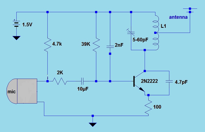
This simple FM (frequency modulation) transmitter is powered only by a 1.5V battery and utilizes a single transistor. The frequency of this transmitter is controlled by the L-C resonance circuit and operates within a range of 80 to 110...
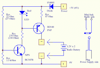
A solar cell radio utilizes a 3V power supply, which can be provided by either a single 3V battery or two 1.2V Ni-Cad batteries connected in series. The battery is non-removable, and the device features a mini jack socket...
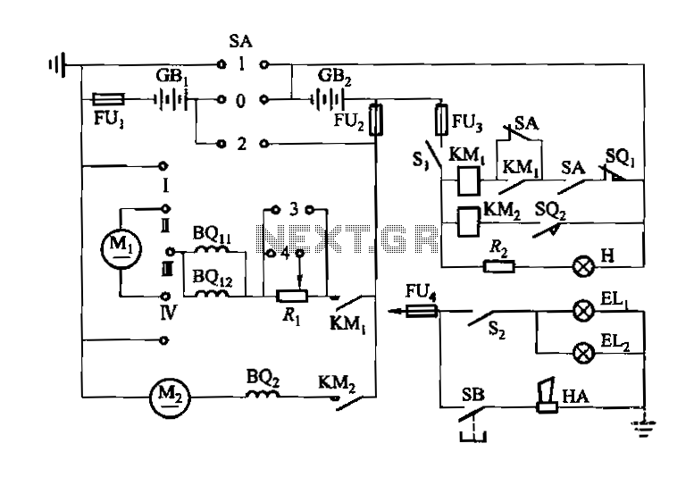
Denote cam controller SA 1 contact closure case. M1 is 1.35 kW driving motor, M2 is a 4 kW pump motor. The circuit involves a cam controller designated as SA 1, which is responsible for managing the operation of...
A simple 7805 charging circuit designed to recharge smartphones, such as the Incredible model. The circuit design is similar to that of the Minty Boost. The 7805 voltage regulator is a popular component used in various electronic circuits to provide...
This affordable and simple-to-construct NiCd/NiMH battery charger is designed for the automatic charging of various batteries used in numerous applications. Reliable chargers are typically costly, while inexpensive chargers that come with original equipment often fail to charge cells correctly,...