
Intelligent NiCd/NiMH Battery Charger
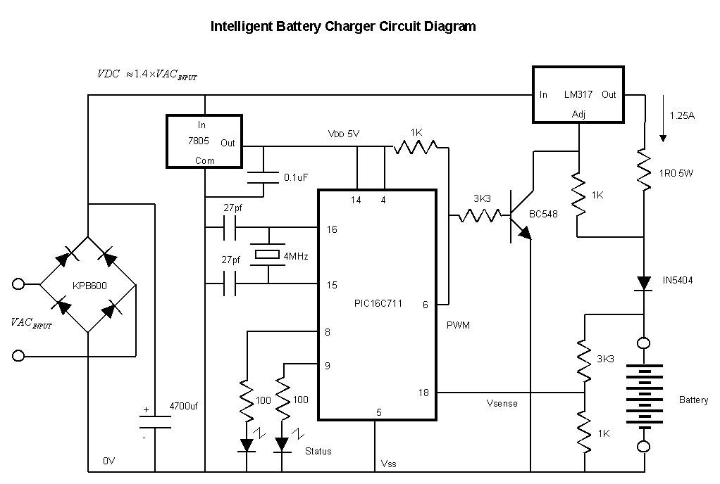
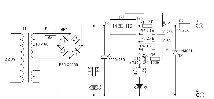
The NiCd/NiMH battery charger circuit typically consists of several key components, including a transformer, rectifier, voltage regulator, and a microcontroller or comparator for monitoring battery voltage and temperature. The transformer converts the mains voltage to a lower AC voltage suitable for charging. The rectifier, often a bridge rectifier configuration, converts the AC voltage to a pulsating DC voltage, which is then smoothed by a filter capacitor to provide a steady DC output.
The charging process is controlled by a microcontroller or a dedicated integrated circuit that monitors the voltage across the battery terminals. This component is crucial for implementing a smart charging algorithm, which may include constant current (CC) and constant voltage (CV) phases. During the CC phase, the charger supplies a fixed current until the battery reaches a predefined voltage threshold. The circuit then transitions to the CV phase, where the voltage is held constant while the current gradually decreases as the battery approaches full charge.
In addition to voltage monitoring, temperature sensing may be incorporated to prevent overheating, which can lead to battery damage or failure. Thermistors or temperature sensors can be placed in proximity to the battery pack, and the microcontroller can adjust the charging current or halt the charging process if excessive temperatures are detected.
Furthermore, the design may include indicators such as LEDs to provide visual feedback on the charging status. A green LED may indicate that the battery is fully charged, while a red LED could indicate that charging is in progress.
Safety features are also paramount in the design of this charger. Over-voltage protection, short-circuit protection, and reverse polarity protection can be implemented using additional circuit elements such as fuses, diodes, and protection ICs.
Overall, this NiCd/NiMH battery charger circuit represents an efficient and cost-effective solution for charging a variety of battery types, enhancing their longevity and performance through intelligent charging techniques.This cheap and easy to build NiCd/NiMH Battery Charger is suitable for automatically charging a wide range of batteries for many applications. Proper chargers are usually expensive and cheap chargers supplied with the original equipment often incorrectly charge the cells and dramatically shorten their life.
This ˜intelligent charger was designed for high cu.. 🔗 External reference
Related Circuits
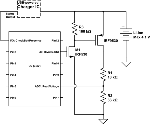
Currently using the PIC24FJ128GA010, there is a plan to utilize an Input/Output port to connect a 4.2 V LiPo battery and monitor the voltage to ensure it does not drop below 3.7 V. It is advised to avoid digital...
The following circuit illustrates a simple battery charger equipped with a temperature sensor. This circuit is based on the LM350 integrated circuit. Features include negative... The circuit utilizes the LM350 voltage regulator IC, which is known for its ability to...
NiCd battery charger schematic and description. This NiCd battery charger circuit can charge 12V, 6V, and 9V battery packs. The NiCd battery charger circuit is designed to efficiently charge nickel-cadmium (NiCd) batteries, specifically those with voltage ratings of 12V, 6V,...
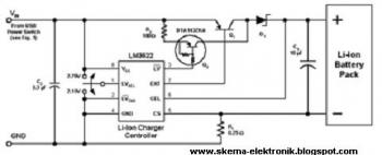
Charger for all battery types power supply. This lithium battery charger circuit is dedicated to charging lithium batteries. It uses two chips: the voltage regulator LM317T and ICL7665, which warns microprocessors of overvoltage and undervoltage conditions. Charging is completed...
This is a simple NiCd battery charger powered by solar cells. A solar cell panel or an array of solar cells can charge a battery at more than 80% efficiency, provided the available voltage exceeds the fully charged battery...

The CMOS 4001 consists of four independent two-input NOR gates. These gates are organized into two pairs. Gates 1 and 2 are connected to form a latching circuit. When the alarm is triggered, they will latch and activate the...