
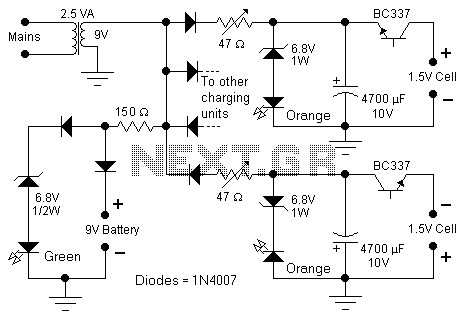
Ni-Cad Charger for Solar Cell Radio by BD140

The solar cell radio operates by converting sunlight into electrical energy, which is then used to power the device or charge the internal battery. The incorporation of a 3V power supply, whether through a single battery or two Ni-Cad batteries, allows for efficient operation of the radio's components, including the receiver, amplifier, and speaker.
The non-removable battery design may pose challenges for users, as it limits the ability to replace the battery once it is depleted. This aspect necessitates a robust charging system to ensure longevity and reliability. The mini jack socket serves as the charging interface, allowing users to connect an external power source when sunlight is insufficient for charging.
In terms of circuit design, the solar cell radio would include a solar panel, a charge controller, a battery management system, and the radio circuitry. The solar panel is responsible for harvesting solar energy, while the charge controller regulates the voltage and current flowing to the battery, preventing overcharging and ensuring safe operation. The battery management system monitors the battery's state of charge and health, optimizing performance and extending battery life.
The radio circuitry typically consists of an RF front end, demodulator, audio amplifier, and speaker. The RF front end is responsible for tuning into radio frequencies, while the demodulator extracts audio signals from the received radio waves. The audio amplifier boosts the audio signals before they are sent to the speaker, allowing for clear sound reproduction.
Overall, the design of the solar cell radio emphasizes sustainability and convenience, though careful consideration must be given to the charging mechanism and battery management to enhance user experience and device longevity.A solar cell radio used a 3V (or two 1.2V) Ni-Cad battery in it. The battery can not be removed. It use a mini jack socket for charging. Its quiet difficult. 🔗 External reference
Related Circuits
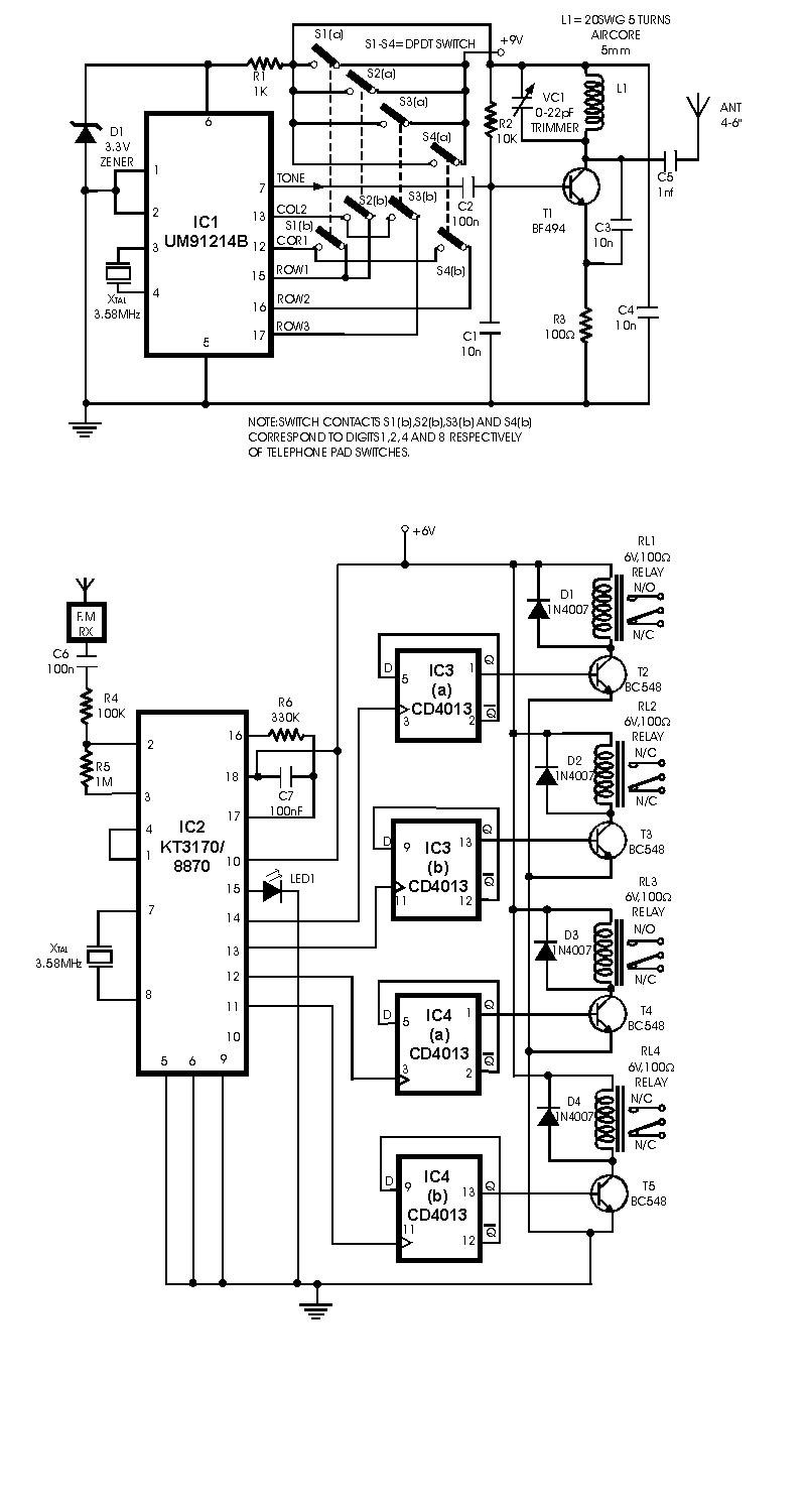
This circuit differs from similar circuits in view of its simplicity and a totally different concept of generating the control signals. Usually remote control circuits make use of infrared light to transmit control signals. Their use is thus limited...
The above circuit is a precision voltage source and contains a temperature sensor with a negative temperature coefficient. Meaning, whenever the surrounding or battery temperature increases, the voltage will automatically decrease. The temperature coefficient for this circuit is -8mV...
Unlike many units, this battery charger continuously charges at maximum current, tapering off only near full battery voltage. In this unit, the full load. This battery charger is designed to operate with a continuous charging mechanism, maintaining the maximum current...
This is a charger circuit designed for both NiCd and NiMh batteries. An old commercial handheld transceiver powered by a 12-volt NiCd battery pack (comprising 10 button cells, each with a capacity of 280mAh) was acquired. The battery, which...
Most surviving TR-1 radios no longer function. Many collectors prefer to maintain them in their original condition to preserve authenticity. However, there may come a time when one wishes to hear the radio play. Before proceeding with any modifications,...
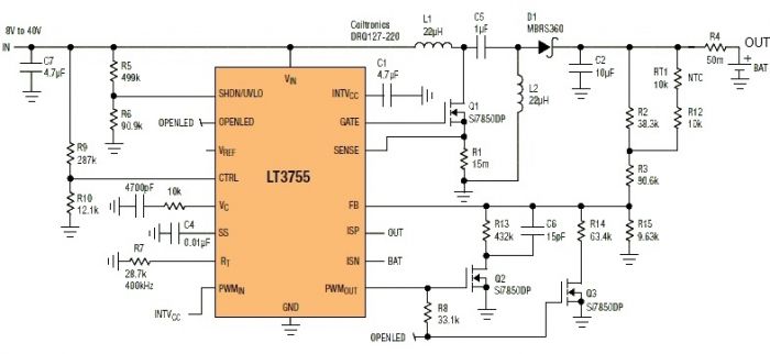
This Sealed Lead Acid Battery Charger is designed using the LT3755 DC-DC controller. The LT3755 is a DC-DC controller that operates as a constant-current source and supports a wide input voltage range from 4.5 to 40 volts, providing a...