
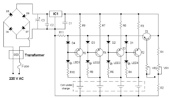
Nickel-Cadmium (NiCd) Battery Charger
The circuit consists of several key components that facilitate the conversion of AC voltage from the mains supply into a suitable DC voltage required for charging batteries. The primary element is the transformer, which steps down the high AC voltage to a lower level. Following the transformer, a rectifier circuit, typically composed of diodes, converts the AC voltage to pulsating DC.
To smooth out the pulsating DC, a filter capacitor is employed, which reduces voltage ripple, providing a more stable DC output. The output of the rectifier and filter circuit is then regulated to ensure that the voltage remains constant despite variations in the input voltage or load conditions. This is often achieved using a voltage regulator IC, which can maintain the output voltage within specified limits.
Additionally, the circuit may include protection features such as a fuse or circuit breaker to prevent damage from overcurrent conditions. A charging control circuit may also be implemented to monitor the battery voltage and current, ensuring that the battery is charged efficiently and safely, preventing overcharging.
Overall, this charger circuit is designed to provide a reliable and efficient method for charging rechargeable batteries, ensuring optimal performance and longevity of the battery cells.The circuit diagram shows a regular charger being powered by an AC input source, intended for charging batteries. This type of rechargeable batteries are.. 🔗 External reference
Related Circuits

The battery should charge up to 14 volts. A reading of 10.7 volts indicates that one cell is shorted. A good way to diagnose this further is to look at the water level in the cells. The shorted cell...
Charger for NiCd batteries power supply. This is a car NiCd battery charger circuit that can charge any Ni-Cd battery between 4.8 and 4.4 volts from a classic 12 volts car battery. The charging current is constant and can...
The circuit described is suitable for indicating the capacity of a battery using a low-cost electric clock. By connecting a resistor across the battery terminals, the battery discharges at a faster rate than it would with the clock alone....
The circuit diagram of a simple and straightforward 12 V battery charger is presented here. This circuit can be utilized to charge various types of 12V rechargeable batteries, including car batteries and motorcycle batteries. The 12 V battery charger circuit...
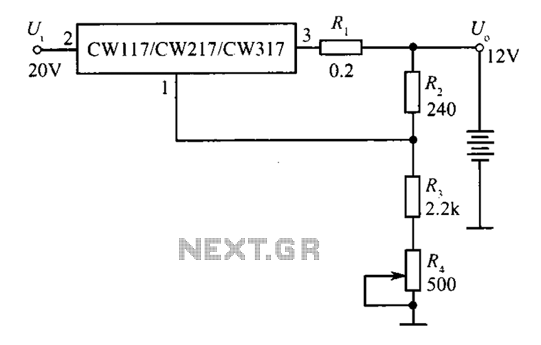
A 12V constant voltage charger is depicted. The power supply circuit shares the same basic design. The resistor R1, valued at 0.2 ohms, serves a limiting function, effectively increasing the internal resistance of the charger, which in turn reduces...
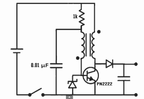
Excellent Joule thief circuit idea! The Joule Thief is a simple yet effective circuit designed to extract usable voltage from low-voltage power sources, such as depleted batteries. This circuit operates on the principle of boosting voltage through the use...