
how to make car battery charger

The 12 V battery charger circuit typically consists of several key components that work together to ensure efficient charging of the batteries. The primary components include a transformer, a rectifier, a voltage regulator, and a charging control circuit.
1. **Transformer**: The transformer steps down the input AC voltage to a lower AC voltage suitable for charging a 12 V battery. It is crucial to select a transformer with an appropriate rating to handle the current required for charging.
2. **Rectifier**: The rectifier converts the AC voltage from the transformer into DC voltage. A bridge rectifier configuration is often used, which consists of four diodes arranged in a bridge format. This configuration allows for full-wave rectification, providing a smoother DC output suitable for battery charging.
3. **Voltage Regulator**: To prevent overcharging and ensure that the battery receives a stable voltage, a voltage regulator is employed. Commonly used regulators include the LM7812 or similar linear voltage regulators, which maintain the output voltage at a constant level despite variations in input voltage or load conditions.
4. **Charging Control Circuit**: This circuit monitors the battery voltage and adjusts the charging current accordingly. It may include components such as resistors, capacitors, and possibly a microcontroller for more advanced control. The goal is to terminate the charging process once the battery reaches its full charge state, thereby prolonging battery life and preventing damage.
5. **Protection Features**: Additional protective components, such as fuses or circuit breakers, can be integrated into the design to safeguard against overcurrent conditions. Furthermore, heat sinks may be employed on the voltage regulator to dissipate excess heat generated during operation.
The overall layout of the circuit should be carefully designed to minimize noise and interference, ensuring stable operation. Proper PCB design techniques, such as short trace lengths and adequate grounding, should be implemented to enhance performance and reliability.Here is the circuit diagram of a simple and straight forward 12 V battery charger circuit with diagram. This circuit can be used to charge all type of 12V rechargeable batteries including car batteries and motorcycle batteries.
🔗 External reference
Related Circuits
A constant-voltage active load can function as a battery during the charge cycle. The load voltage can be adjusted from 5 to 35V using potentiometer PV, simulating batteries with voltages ranging from 6 to 32V. In the testing of...
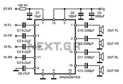
The following circuit illustrates a 35W quadruple amplifier and a 2 x 25W bridge amplifier based on the TDA7375 integrated circuit (IC). This circuit requires a minimal number of external components. Although initially designed for car applications, it can...
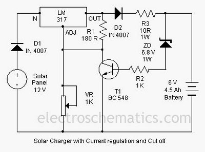
A solar charger circuit is designed to charge lead-acid batteries or nickel-cadmium (Ni-Cd) batteries using solar power. This circuit captures solar energy to charge a 6-volt, 4.5 Ah battery for various applications. It features voltage and current regulation along...
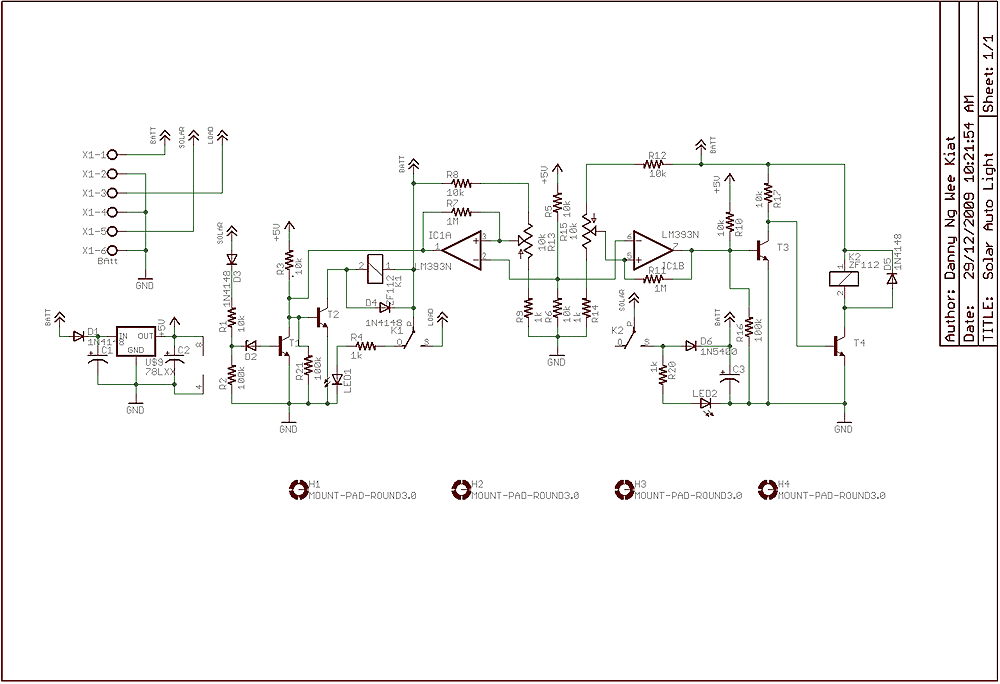
Few years back, I had been working on a project for solar auto lighting. The light will turn on when the solar panel voltage drop below a set point indicating that it is dark. The detection is done by...
A low-cost DC adapter can be utilized to construct a stabilized and uninterruptible 9V power supply. For safety and cost-effectiveness, a simple unstabilized 12V DC adapter serves as the power source; a universal adapter set to 12V will also...

The concept involved removing the center page from a magazine and cutting it into four pieces to create a card suitable for a filing system. The front side of each card provided connections to the integrated circuit (IC), while...