
Nikon IR-Remote Control

The schematic for the IR remote control circuit involves a few key components and connections. The ATtiny13 microcontroller serves as the core of the design, interfacing with the existing remote control's circuitry. Power is supplied through the two AAA batteries, providing a stable voltage to the ATtiny13 and the IR LED. The IR LED is connected to one of the digital output pins of the ATtiny13, allowing it to transmit the modulated IR signals.
The switch matrix is reconfigured to connect the buttons to the input pins of the ATtiny13. Each button press is detected using pull-up resistors, ensuring a high state when unpressed and a low state when pressed. The microcontroller's firmware is programmed to recognize button presses and trigger the appropriate IR signal sequence.
The SENDBURST subroutine is critical for generating the correct timing for the IR signals. The timing is adjusted to ensure that the transmission bursts are modulated onto the 38kHz carrier frequency. The ATtiny13's internal timer can be utilized to create precise delays, ensuring that the bursts are sent at the right intervals. The LEDSTAT register controls the state of the IR LED, toggling it on and off according to the defined protocol.
In summary, this IR remote control circuit for the Nikon DSLR camera is a practical and straightforward project that leverages existing components and simple firmware to achieve effective remote shutter control. The design is flexible, allowing for personal modifications and improvements, making it suitable for hobbyists and electronics enthusiasts.IR remote control for my Nikon DSLR camera. Not that I absolutely need one, surely I don`t need it bad enough to get one for about ‚¬30 or ‚¬40 from e-bay. However it would make a nice little in-between project. Big Mike explains the very easy protocol used by the original Nikon remote controls ML-L1 or ML-L3 on his web site.
I happen to be very good at re-inventing the wheel, therefore I have designed and built my own version. It just so happens that I`ve bought myself an ATMEL STK-500 kit, so this was a perfect test case for it.
I`ve ordered some samples of the ATtiny13 processor from Atmel, which can be operated without external clock. Even this small processor is a bit of overkill for the job at hand, but this was the smallest processor I could find.
On the above mentioned web site there are some pictures of other people who have built their own versions of an IR remote control in several different appearances. Personally I think building the remote control in an empty tic-tac box is a great idea! However I`ve chosen to build it in an obsolete existing remote control. Simply because it was at hand and because it can hold two standard AAA batteries. I`ve rewired the switch matrix in such a way that I now can press any of the keys to fire the shutter.
Feel free to use your imagination if you want to build your own version of the IR remote control. There is no PCB for this easy design. In my case the output amplifier was already available in the existing remote control. I`ve only removed the original IC from the board and added the ATtiny13. I don`t have the original specification of the Nikon remote control protocol. The information on Big Mike`s web site was also derived from reverse engineering. What I understand from that information is that the timing of the signals is not particularly critical. Therefore I have taken the liberty to adjust some of the times in the waveform to match exact multiples of one clock period of the 38kHz carrier, which is 26, 3 µs.
The bursts are modulated on a 38kHz carrier. Care has been taken to keep the phase of the carrier between the bursts as constant as possible in order to achieve the optimal sensitivity of the IR receiver in the camera. In my case I could fire the shutter even at a distance of about 12 metres. It probably reaches even further, but that`s as far as could get away from the camera without getting wet from the rain outside.
The software consists of only two subroutines, one of which is carefully designed in order to generate precise timings. Well, as precise as they can get of course if you consider that the internal RC oscillator of the ATtiny13 can deviate from the nominal frequency by as much as 10%.
I have run some tests by deliberately altering the timing without any problems. I have also tried 2 other ATtiny13 processors and they gave exactly the same results. Therefore I doubt that you`ll ever have to adjust the timing of the burst routine. The SENDBURST subroutine consists of a main loop which always takes 26. 3 µs to execute. Wait, I tell a lie! Not always, the first time through the loop is a bit shorter to compensate for the subroutine call and return overhead. Please note that SENDBURST is the entry point of the subroutine. The subroutine is the same for marks and for spaces. The LEDSTAT register indicates whether we`re sending a mark of a space. A value of 0b11111101 will leave the LED extinguished, while a value of 0b11111111 will turn the LED on/off at a frequency of 38kHz.
;- ; Send BCOUNT pulses. ; BCOUNT : Holds number pulses to send ; BDELAY : Holds high/low delay times ; LEDSTAT : Holds mark (11111111) space (11111101) flag ;- NEXTPULSE: LDI BDELAY, BURST0 ; Reload delay counter for Low period SENDBURST: DEC BDELAY ; Low period delay loop BRNE SENDBURST 🔗 External reference
Related Circuits
The television screen used at home features built-in speakers; however, since it functions as a computer display, it lacks an infrared receiver. This limitation prevents volume adjustment using the TV receiver remote. A recent acquisition of Stellaris LaunchPad development...
This is a circuit for controlling the speed of small DC motors; it works nicely as a speed controller for an HO or N gauge model railroad. More: The left half of the 556 dual timer IC is used...
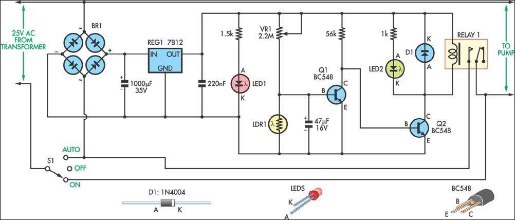
This circuit was designed to control a pump in a garden pond, enabling it to automatically activate at dawn and deactivate at dusk. The circuit utilizes a light-dependent resistor (LDR) to detect ambient light levels, which serves as the primary...
In the production field, automatic detection of water levels and control is a critical technology for industrial process control, significantly enhancing the level of automation in these processes. In everyday life, water supply has traditionally been managed manually, which...
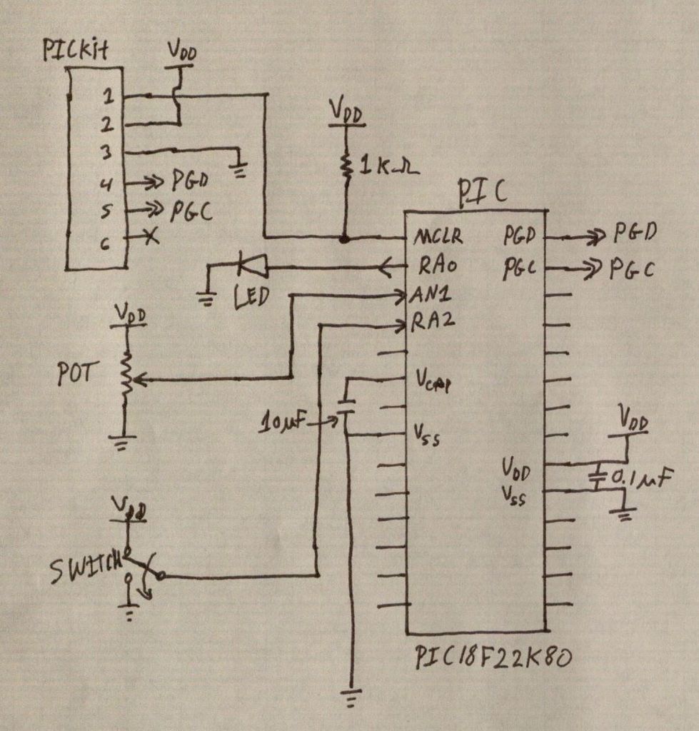
PIC microcontrollers are a highly useful and versatile component for various electronic projects. They are affordable and readily available. PIC microcontrollers are embedded systems that serve as the central control unit in a wide range of electronic applications. Their architecture...
A fluorescent starter bimetal can be utilized as a temperature sensing element for thermostatic control. This component consists of a double metal sheet designed for temperature sensing, resulting in a simple circuit that is easy to manufacture, although it...