
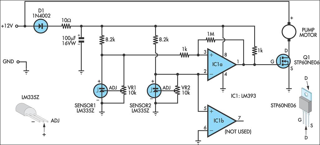
Light-Controlled Pond Pump
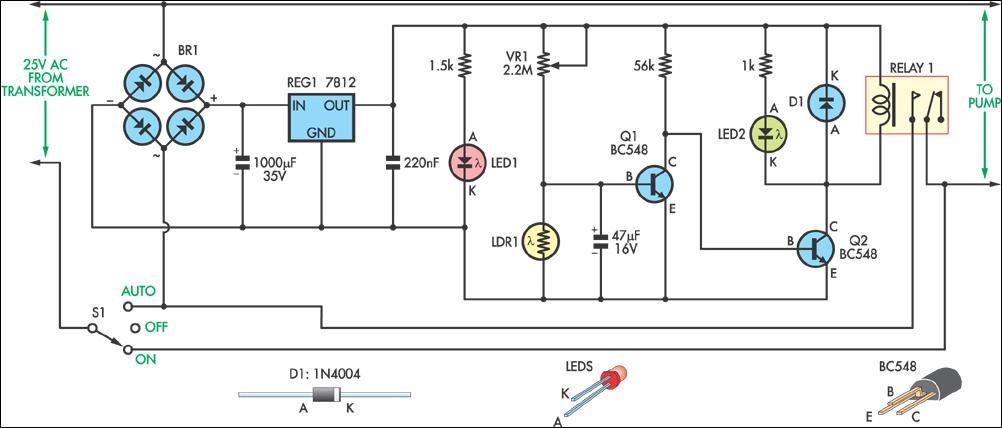
The circuit utilizes a light-dependent resistor (LDR) to detect ambient light levels, which serves as the primary sensor for determining day and night conditions. The LDR is connected in a voltage divider configuration with a fixed resistor, creating a varying voltage output that changes based on the light intensity. This output is fed into a comparator circuit, which may consist of an operational amplifier configured to switch states when the voltage crosses a predetermined threshold.
The output of the comparator is connected to a relay or a transistor switch, which controls the power supply to the pump. When the light level drops below the threshold at dusk, the comparator output changes state, activating the relay and thus powering the pump. Conversely, as dawn approaches and light levels increase, the LDR's resistance decreases, causing the comparator to deactivate the relay and turn off the pump.
Additional components may include a potentiometer for adjusting the threshold sensitivity, allowing for customization based on the specific environmental conditions of the garden pond. A diode may also be included in parallel with the relay coil to prevent back EMF from damaging the circuit when the relay is switched off. This design ensures that the pump operates efficiently, conserving energy and maintaining optimal water levels in the pond without manual intervention.This circuit was constructed to control the pump in a garden pond, so that it automatically turns on at dawn and off again at dusk. Not only does this mea.. 🔗 External reference
Related Circuits
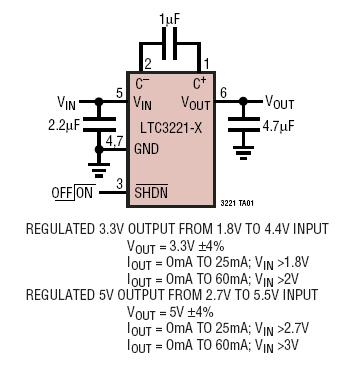
The LTC3221 family consists of micropower charge pump DC/DC converters that deliver a regulated output of up to 60mA. The input voltage range is from 1.8V to 5.5V. With an extremely low operating current of 8µA typical at no...
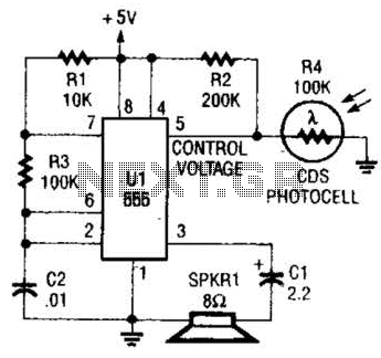
This circuit can be utilized as a light detector and potentially as a tool for individuals with visual impairments. The frequency of the oscillator is influenced by the level of illumination received by LDR4. The circuit operates by employing a...
This device emits intermittent beeping for approximately two seconds when a whistle is detected within a range of several meters. The first two inverters in IC1 function as audio amplifiers. IC1A consistently amplifies the signal captured by a small...
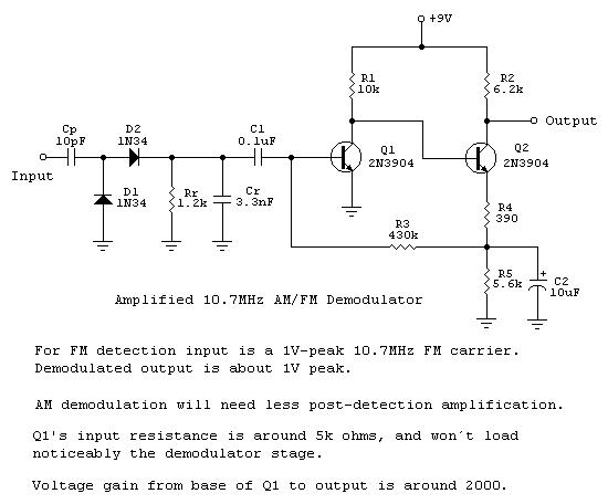
Frequency-to-voltage converters are integral components in various instrumentation circuits and are also utilized in radio applications as FM demodulators. A notable configuration for these applications is the Diode Charge Pump circuit (DCP), which additionally serves as an AM detector....
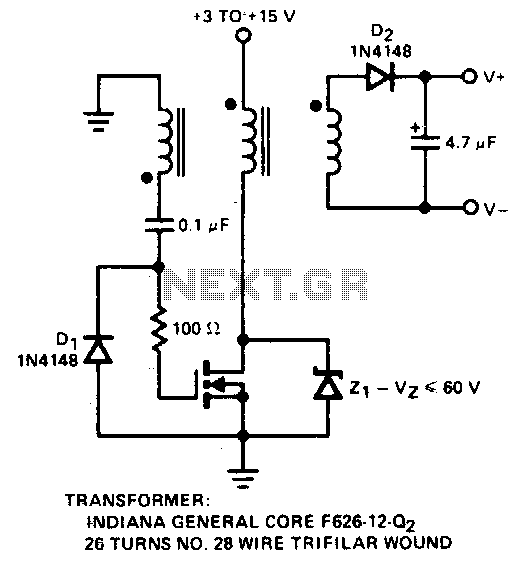
A simple method for generating a low-power voltage supply of opposite polarity from the main supply. A self-oscillating driver produces pulses at a repetition frequency of 100 kHz. When the VMOS device is off, capacitor C is charged to...
A solar water heating pump controller is an essential component in most solar water heating systems, whether DIY or commercially produced. Its primary function is to activate the pump when the fluid in the solar panel is at a...