
NiMH Battery Charger Circuit

The battery charger circuit described utilizes a transformer to step down the AC voltage, which is then rectified by the full-wave bridge rectifier. This configuration ensures that the output voltage is always positive, suitable for charging the battery. The smoothing capacitor C1 filters the rectified output voltage, reducing ripple and providing a stable DC voltage to the subsequent circuit components.
The current regulation mechanism is critical for the safe charging of Nickel Metal Hydride batteries, which can be damaged by excessive current. Resistor R1 is strategically chosen to set the desired charging current at 140 mA. The Epitaxial Darlington transistor TIP 127 is selected for its high current gain, allowing it to effectively control the output current with minimal input base current.
The LED indicator is a vital feature of the circuit, providing visual feedback regarding the charging status. When a battery is connected, and the input voltage is adequate, the LED illuminates, signaling that the charger is operational. The combination of R2 and the LED ensures that the base current to T1 is maintained at an optimal level, preventing the transistor from going into saturation, which could lead to an uncontrolled increase in charging current.
Overall, this simple yet effective battery charger circuit exemplifies fundamental electronic principles, including voltage regulation, current limiting, and visual status indication, making it suitable for safely charging Nickel Metal Hydride batteries in various applications.A simple battery charger for the Nickel Metal Hydride battery that requires current regulated charging. The charger provides 140 mA current for quick charging of the battery. Power supply section consists of a 0-18 volt AC 1 Ampere step-down transformer, a full wave bridge rectifier comprising D1 through D4 and the smoothing capacitor C1.
Current regulation is achieved by the action of R1, R2 and the Epitaxial Darlington PNP transistor TIP 127. Resistor R1 keeps the charging current to 140 milli amperes. LED and resistor R2 plays an important role to control the base current of T1 and thus its output. Around 2. 6 volts drop develops across the LED which appears at the base of T1. Emitter base junction of T1 drops around 1. 2 volts. So 2. 6 1. 2 volts gives 1. 40 volts. So the current passing through R1 will be 1. 40 V / 10 = 0. 14 Amps or 140 Milli Amps. The LED act as the charging status indicator. LED lights only if the battery is connected to the output of circuit and the input voltage is normal.
🔗 External reference
Related Circuits
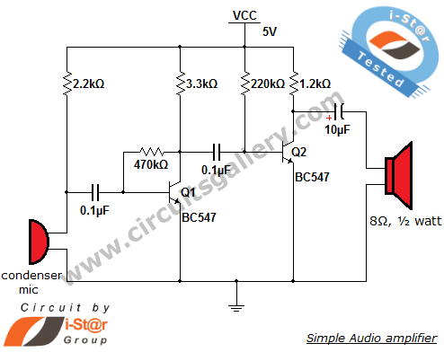
This circuit diagram is a simple and effective design for amplifying weak signals from a capacitive condenser microphone. It is suitable for sound sensing applications and various automatic robotic sensors. While a more complex audio amplifier circuit using the...
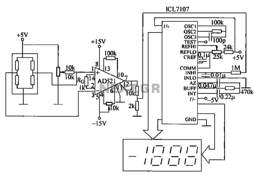
A pressure sensor circuit features a pressure sensor with a nominal resistance of 120 ohms. The amplifier circuit utilizes an AD521 operational amplifier with a gain of 100. It includes resistor components Rs and Rc, along with a decision-making...
The article describes the process of building a charger controller board and programming the AVR microcontroller. A Li-Ion battery is needed for practice; the example battery mentioned has withstood considerable abuse. Knowledge of the battery's specifications, such as maximum...
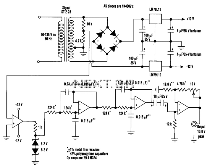
A highly stable 60-Hz sine wave can be delivered with this circuit, which offers a different and much simpler approach to achieving a stable amplitude. Capacitor coupling in the last stage removes any DC component caused by unequal Zener...
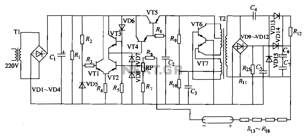
The DC power supply is a helium-neon laser excitation power supply, which is currently the most commonly used type of power supply. It is utilized in laser printers. The circuit includes a power transformer (T1), a high-voltage transformer (T2),...
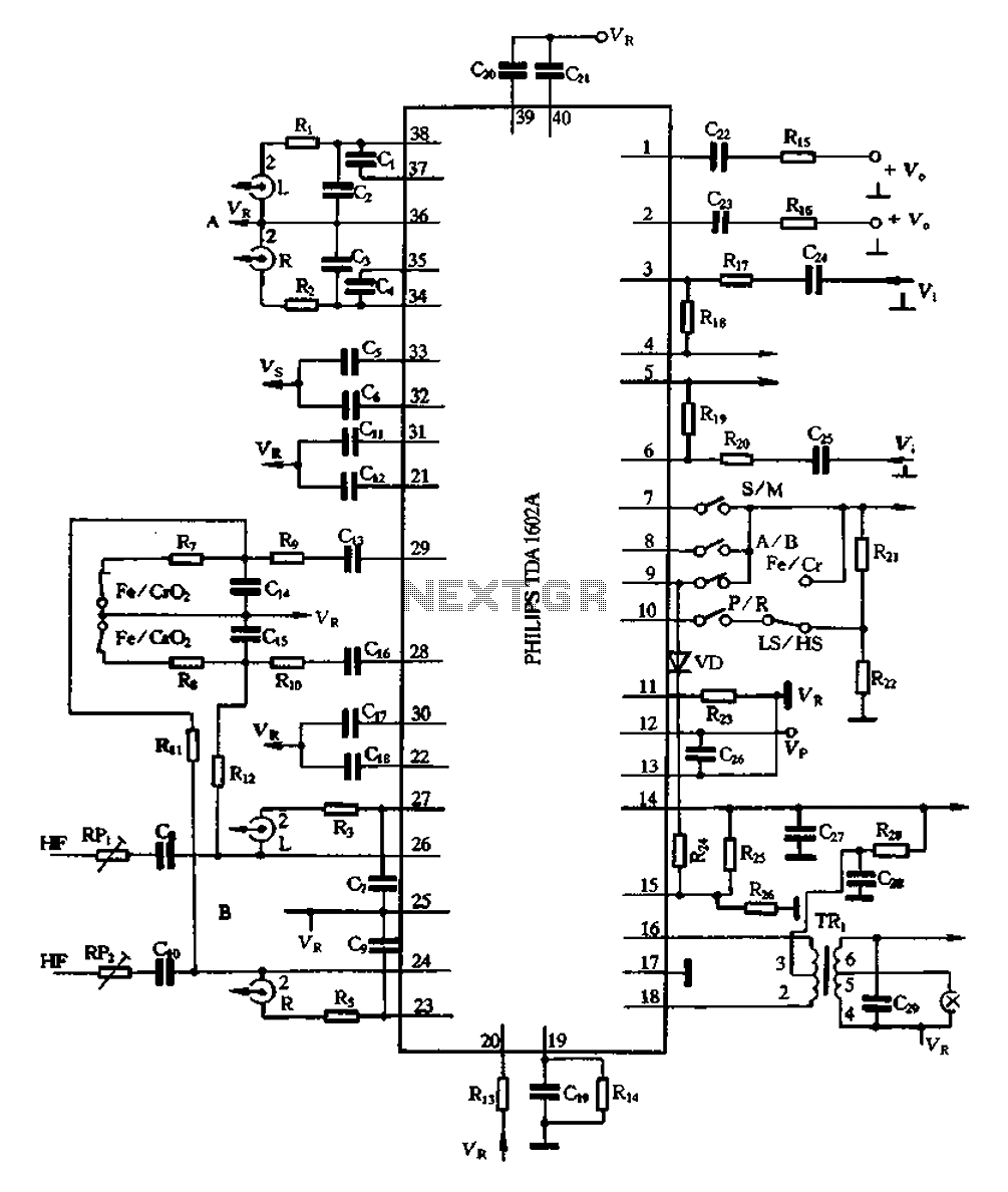
The A1602A is a 40-pin dual in-line package that functions as a playback preamplifier. It utilizes linear low-noise amplifiers with a voltage gain of 26.4 dB. Each channel has a separate discharge sound preamplifier, selected by an electronic switch...