
build lithium ion battery
The charger controller board is designed to manage the charging of Li-Ion batteries effectively, integrating a microcontroller to handle various parameters and functionalities. The ATMEGA8 microcontroller acts as the core of the system, enabling programmable control over the charging process. The use of a PWM output for current and voltage control allows for precise management of the charging cycle, ensuring optimal battery performance and longevity.
The inclusion of a UART interface facilitates real-time communication between the charger and a connected PC, allowing users to monitor charging status and parameters easily. This feature is particularly beneficial for developers and engineers looking to analyze the charging process or troubleshoot issues. The choice of an 18V @ 3.5A power supply ensures that the system has sufficient headroom to handle the maximum charge voltage requirements, while the large inductor and capacitor combination provides stability, minimizing voltage fluctuations during operation.
To enhance the usability of the charger, the design incorporates an 8-point DIP switch for parameter selection, allowing users to tailor the charging settings to specific battery types and requirements. The variable resistor for setting charge current in "Custom" mode adds further flexibility, enabling users to optimize charging based on their specific needs.
The construction method, utilizing a foil grid board, demonstrates a practical approach to prototyping, allowing for easy modifications and adjustments during the development phase. The attention to detail in labeling and documentation enhances the project's overall quality, ensuring that users can replicate or modify the design as needed.
Overall, this charger controller board serves as a robust platform for managing Li-Ion battery charging, combining advanced microcontroller capabilities with user-friendly features and a flexible design approach.The article now describes how to build a charger controller board and how to program the AVR microcontroller. You should have a LiIon battery you can practice on - my practice battery is still alive and well despite considerable abuse.
The more you know about the battery the better: Maximum charge voltage and amps (sometimes printed on the case), thermistor (yes/no and resistance - they are not always 10K) and Smart Battery or not. In addition to the charge controller a DC supply capable of providing at least 2 volts more than the max cell voltage (14. 6 volts in my case) at the desired current is required. At the capacities I want you are out of the "Wall wart" category. I found a laptop supply for a Dell rated at 18V @3. 5A. The board is fabricated using easily obtainable components - refer to the parts list in the Atmel App Note.
I made some substitutions and marked the schematic up accordingly. The ATMEGA8 is a new release and has 8K Flash, 1K RAM in a 28 pin narrow DIP package and can be clocked up to 16MHz. If you are willing to eliminate the Smart Battery interface and delete some of the debug code the code could be made to fit in an AT90S4433 as per the original Atmel design.
The microcontroller software used is GCC version 3. 2. This version is required to accommodate the direct I/O assignments that resulted from the conversion from IAR that was used in Atmels App note. The software is actually a combination of Atmels, converted from IAR, an I2C interface, converted from 68HC11/Imagecraft and my own GCC code.
As a result the program does not read as well as I am used to as 3 different styles are evident. The current / voltage control is managed by a PWM output into a P-Channel MOSFET. A large inductor / capacitor combination is used to stabilize the circuit. The special purpose chargers generally run at much higher frequencies ( 150KHz compared to 15KHz) and can thus use smaller components, not that important in my case. The charger provides a continuous data stream output from the UART for your PC. I send initialization info and continuous charge status information from the charger, and, if a Smart Battery is connected, the battery, that can be viewed on a PC terminal program.
Baud rate is set at 115K but could be lowered as desired. The charger was operational after a weeks part time effort, another few days were spent on the Smart Battery interface and a couple more to document the whole thing. I use a foil grid one side board with foil down. I spot solder most components to the grid and use wire-wrap to wire it up. This board had a requirement for larger power wire which was installed where needed. Notice from the photo that I use homemade wirewrap pin labels - I print them on the printer and push them down over the pins.
Works quite well. I also print out top of board ID labels. This project would be a good candidate for a printed circuit board - I just don`t have any incentive now that my board is working. The microcontroller physical design is pretty much a standard AVR design. A 7. 3 MHz crystal is used (the ATMEGA8 can take up to 16 MHz). I added an 8 point dip switch for battery parameter selection and a variable resistor for setting Charge current in "Custom" mode.
I include a UART interface but did not install the RS-232 interface on the board as I have a very useful cable with a MAX233 built in. You can see from the photo that I have attached a heat sink to the HexFET. I suspect I could get up to 3. 5 to 4 amps without problems with this setup. So far I`ve held back to 2. 5 amps as I have no spare HexFETs in house and don`t feel like doing destructive testing. Read the App note for a good description of how this circuit works. I mounted the power components on the opposite end of the board from the uC and kept three separate grounds (uC, analog, charger power) connected only at a single point.
The op amp circuit used to measure battery voltag 🔗 External reference
Related Circuits

This is a simple yet effective charger for lead-acid batteries. It utilizes a 12-volt car bulb as both a current regulator and a charge status indicator. The described circuit is an innovative approach to charging lead-acid batteries. It employs...
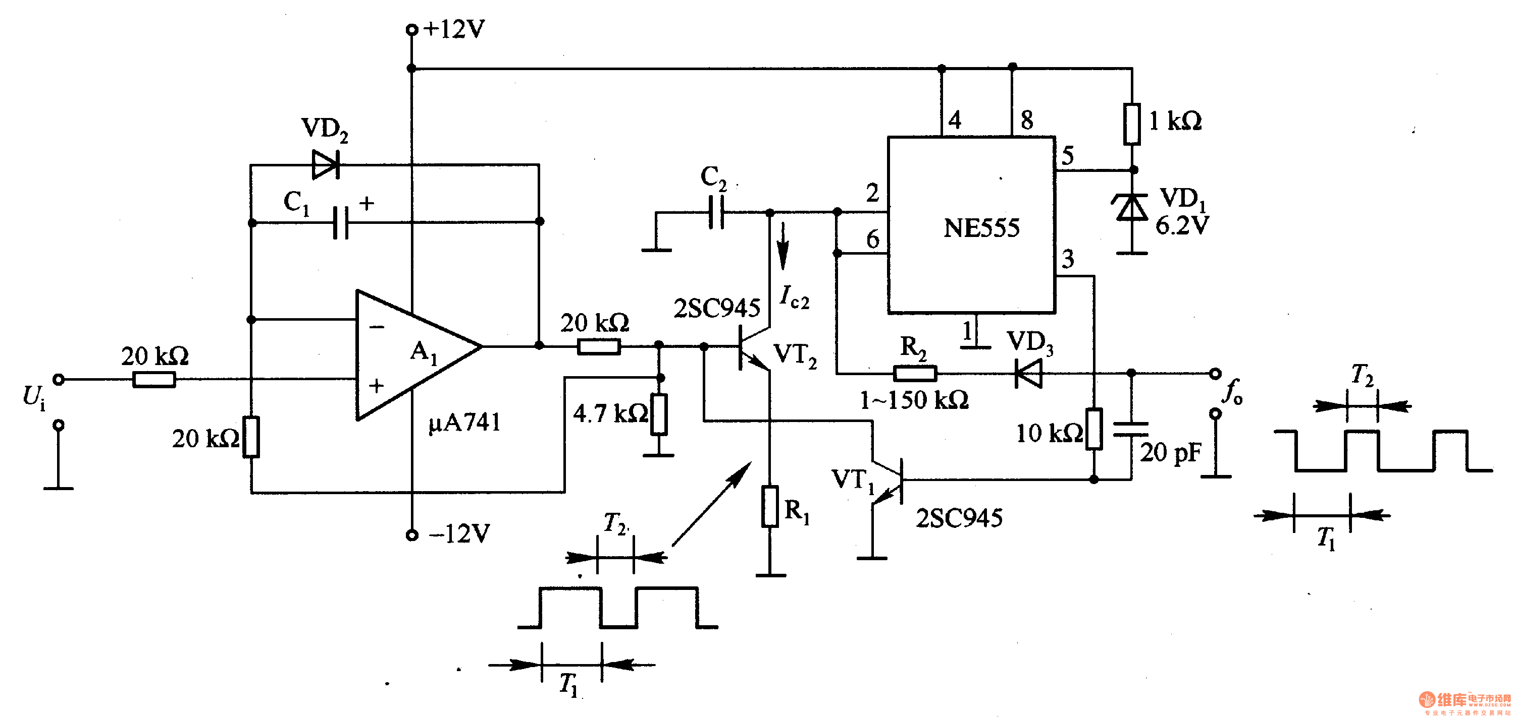
In the circuit, the oscillation frequency of the NE555 is controlled by VT2. When the output at pin 3 is low (during the T1 period), VT1 stops conducting, and VT2 begins to conduct with a current Ic2 flowing through...
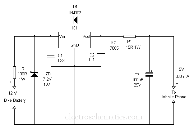
This circuit provides a simple and efficient method to draw current from a motorcycle battery to charge a mobile phone. Most mobile phone battery packs consist of three 1.2-volt cells, resulting in a total voltage of 3.6 volts. For...
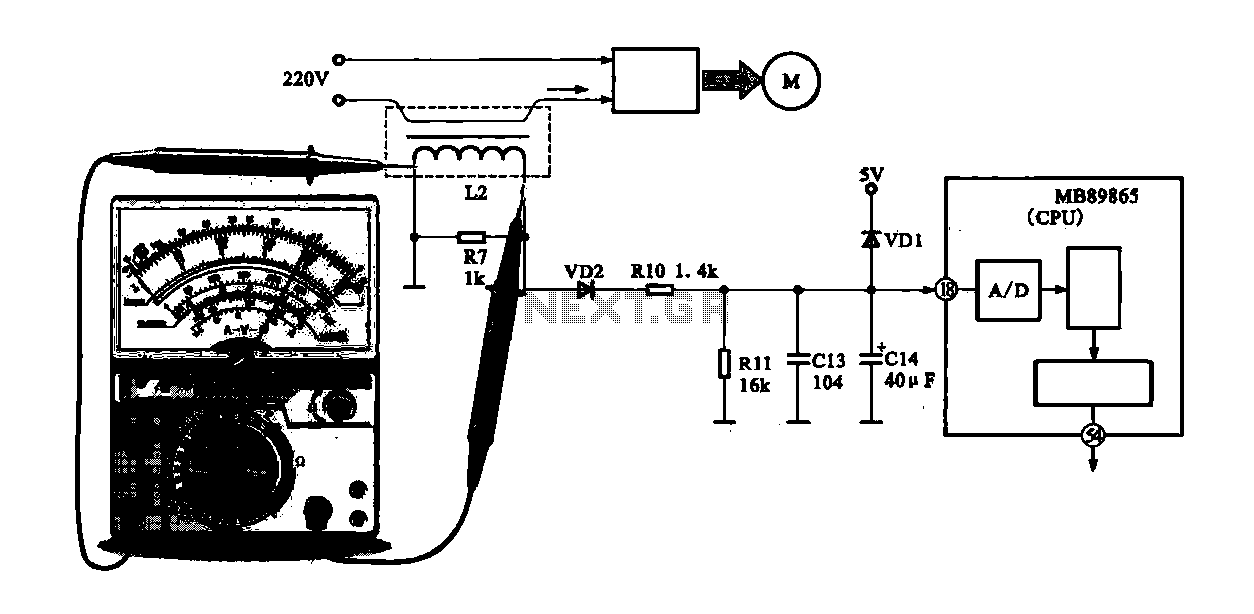
A current-voltage conversion circuit is commonly utilized in current detection applications. An example is the current detection circuit for a ring inverter air conditioner, which primarily serves to monitor the supply current of the compressor motor. Excessive current can...
The simplest polarity protection technique is to connect a series diode to the power line input. The diode conducts only when the power supply is connected correctly. A series diode is an effective method for preventing reverse polarity in electronic...
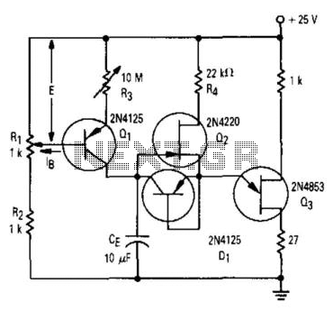
Transistor Q1 and resistors R1, R2, and R3 form a constant current source, with the charge current adjustable to as low as a few nanoamperes. This current is insufficient to activate the UJT, where IP is 0.2 A, unless...