
pt05 diy preamplifier

The circuit design incorporates a fully complementary amplifier configuration, which enhances the performance by balancing the positive and negative signal paths. The cascode circuit is strategically positioned to improve the linearity of the amplifiers, which is crucial for high-fidelity audio applications. By utilizing a transistor array as a voltage reference, the design minimizes current consumption while maintaining stability and low noise levels, which is essential for achieving high-quality audio output.
The voltage gain of 12 is achieved through careful selection of component values and feedback mechanisms within the amplifier stages. This gain is critical for ensuring that the output signal is sufficiently amplified for downstream audio processing or amplification stages.
The linear power supply design is notable for its two-stage voltage regulation approach. The first stage employs a rectifier to convert the AC input to DC, which is then smoothed by filtering capacitors. The two regulator ICs provide a stable output voltage by reducing ripple and noise, ensuring that the amplifiers receive clean power. The shunt voltage regulator in the second stage further refines the output, providing precise voltage regulation and enhancing the overall performance of the preamplifier.
The audio characteristics of the PT05 preamplifier have been carefully tuned to provide a polite sound signature, making it suitable for various audio applications. While the deep bass response may be slightly less pronounced compared to the PT03 model, the overall musicality is improved, with a focus on clarity and detail in the midrange and treble frequencies. This attention to detail in the circuit design and component selection contributes to a well-rounded listening experience, making the PT05 a valuable addition to any audio setup.The next stage is working with the first stage as well it is a fully-complementary. The cascode circuit is also in this place to improve linearity of the amplifiers. Cascode circuit requires a constant reference voltage biasing to make a cascode transistor on. We chose to use a transistor array as a voltage reference. Because it requires less curr ent compared to the use of zener diode, diode and LED, and of course, it has lower noise. The overall voltage gain is set to 12 times. What are the power supply of my PT05 DIY preamplifier. It is a linear power supply with a voltage regulation circuit includes a rectifier and regulator IC amounting 2 pieces per side. It was called a 2. 1 voltage regulation. 2 is 2 stages voltage regulation by 2 regulator ICs. 0. 1 is a shunt voltage regulator. So I called it a 2. 1 voltage regulation. Overall, It would polite sound. The deep bass is slightly less than the PT03. But it gives the better musical. Midrange and treble detailed are done very well. 🔗 External reference
Related Circuits
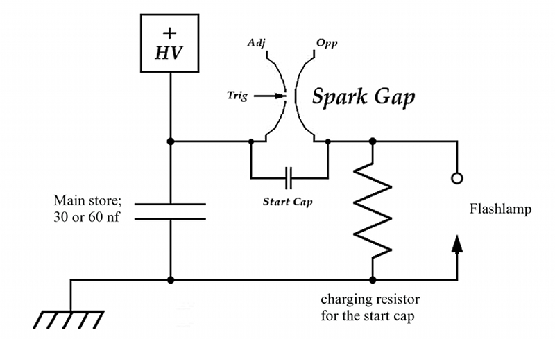
This page outlines the construction of a prototype dye laser designed for initial parameter testing. The primary objective is to determine whether a straightforward design can effectively threshold certain dyes with minimal input energy. Although the theoretical answer is...
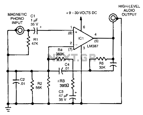
This simple stereo amplifier utilizes a National LM3871C. The pin numbers in parentheses correspond to one channel, while those without parentheses refer to the other channel. The supply voltage can range from +9 to +30 Vdc at approximately 10...
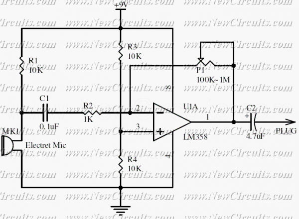
This circuit will be useful if you have an electret microphone that produces a low audio (sound) level and you want to connect it to an amplifier or something like it. The circuit boosts the microphone output voltage to...
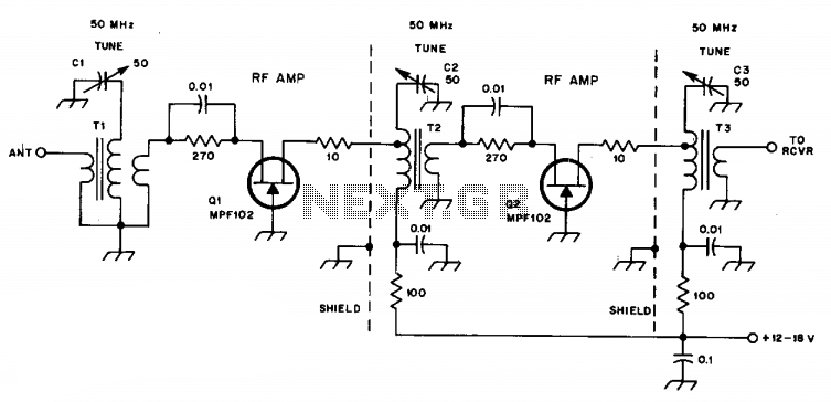
C1, C2, and C3 are miniature ceramic or plastic trimmers. T1 (main winding) has an inductance of 0.34 µH, utilizing 11 turns of No. 24 enameled wire wound on a T37-10 toroid core. The antenna winding consists of one...
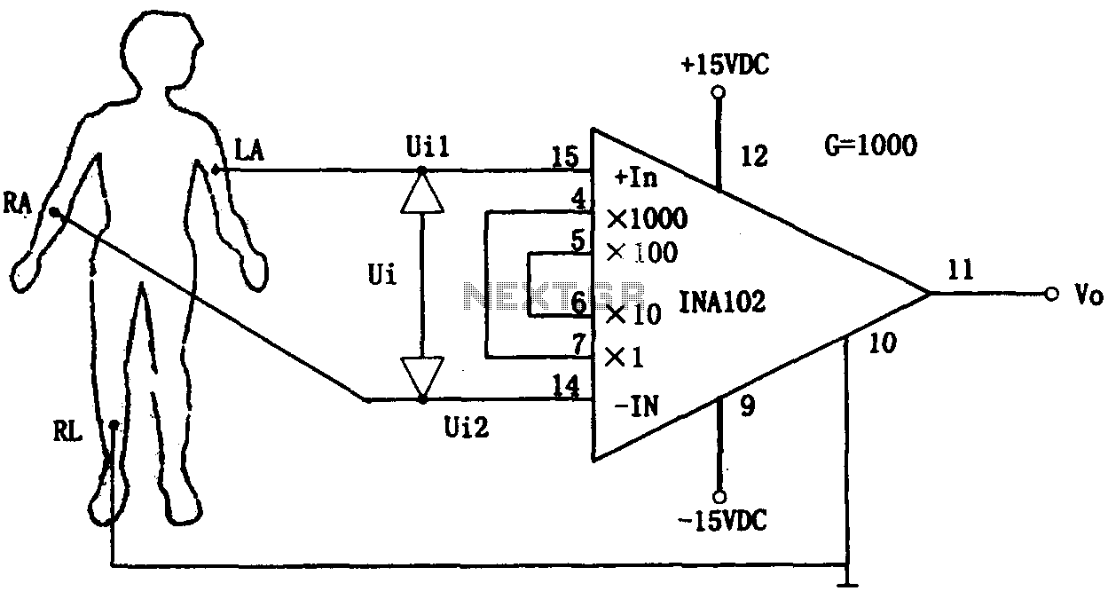
This document outlines a preamplifier circuit designed for measuring human biological signals, such as ECG and EEG. These biological signals are typically weak and require high amplification circuits. The circuit utilizes a low-power integrated operational amplifier, INA102. The INA102...
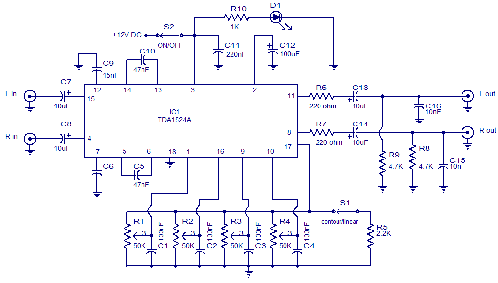
The following circuit illustrates the TDA1524 IC Stereo Preamplifier Circuit Diagram. Features include the ability to control volume, balance, and bass. The TDA1524 is a highly integrated stereo preamplifier IC designed for audio applications. This circuit configuration allows for the...