
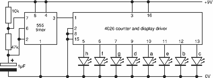
Nite Rider LEDS
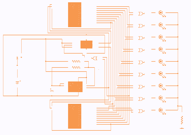
1 555 timer IC4.
1 4027 flip flop IC1.
2 4017 Decade Counter IC2 and IC3.
3 4071 OR gate IC5, IC6 and IC7.
1 470 Ohm resistor 1/4 watt R3.
2 10K resistors 1/4 watt R1 and R2.
1 6.8UF Capacitor 16V C1.
9 Super bright LED's 1 to 9.
1 9V PP3 Battery.
1 single pole switch SW1.
1 Box.
How The Circuit Works.
IC4, C1, R1 and R2 are used for the clock pulse which is fed to both the counters IC2 and IC3 Pin 14.
IC1 is a Flip Flop and is used as a switch to enable either IC2 or IC3 at pin 13.
IC7a detects when either IC2 or IC3 has reached Q9 of the counter pin 11.
IC5, IC6 and IC7a protect the outputs of the counters IC2 and IC3 using OR gates which is then fed to the Anodes of the LED's 1 to 9.
The circuit design of the 'NITE-RIDER' incorporates a series of integrated circuits and components to create a visually striking lighting effect for bicycles. The heart of the circuit is the 555 timer IC (IC4), which is configured in astable mode to generate a continuous clock pulse. This pulse is essential for driving the two 4017 decade counters (IC2 and IC3), which sequentially activate the LEDs.
The 4027 flip-flop (IC1) functions as a toggle switch, allowing the circuit to alternate between the two counters. When one counter reaches its maximum count (pin 11, Q9), it signals the flip-flop to switch and enable the other counter. This creates a back-and-forth lighting effect as the LEDs illuminate in sequence.
The use of three 4071 OR gates (IC5, IC6, and IC7) ensures that the outputs from both counters can be combined and sent to the anodes of the nine super bright LEDs. This arrangement allows for a smooth transition of light from one side to the other, enhancing visibility for cyclists at night.
The circuit is designed to operate efficiently with a 9V PP3 battery, utilizing CMOS technology for low power consumption. This is complemented by the inclusion of resistors (R1, R2, and R3) to limit current and protect the LEDs, and a capacitor (C1) to stabilize the power supply and ensure consistent operation.
In summary, the 'NITE-RIDER' circuit combines innovative design with practical components to provide an effective lighting solution for cyclists, enhancing safety and visibility during nighttime rides. As a keen cyclist I am always looking for ways to be seen at night. I wanted something that was a novelty and would catch the motorists eye. So looking around at my fellow cyclists rear lights, I came up with the idea of 'NITE-RIDER'. NINE extra bright LED's running from left to right and right to left continuously. It could be constructed with red LEDs for use on the rear of the bike or white LED's for an extra eye catcher on the front of the bike. All IC's are CMOS devices so that a 9V PP3 battery can be used, and the current drawn is very low so that it will last as long as possible.
The circuit comprises of ... 1 555 timer IC4. 1 4027 flip flop IC1. 2 4017 Decade Counter IC2 and IC3. 3 4071 OR gate IC5, IC6 and IC7. 1 470 Ohm resistor 1/4 watt R3. 2 10K resistors 1/4 watt R1 and R2. 1 6.8UF Capasitor 16V C1. 9 Super brght LED's 1 to 9. 1 9V PP3 Battery. 1 single pole switch SW1. 1 Box. How The Circuit Works. IC4, C1, R1 and R2 are used for the clock pulse which is fed to both the counters IC2 and IC3 Pin 14. IC1 is a Flip Flop and is used as a switch to enable ether IC2 or IC3 at pin 13. IC7a detects when ether IC2 or IC3 has reached Q9 of the counter pin 11. IC5, IC6 and IC7a protects the outputs of the counters IC2 and IC3 using OR gates which is then fed to the Anodes of the LED's 1 to 9.
🔗 External reference
Related Circuits
The schematic depicts standard light bulbs, indicating the possibility that some bulbs may be burned out. It is currently unclear whether the bulbs can be easily replaced. Further inspection reveals that the bulbs in the HVAC control can indeed...
The circuit shown demonstrates how to power one or two LEDs from a 120-volt AC line by utilizing a capacitor to reduce the voltage and a small resistor to limit the inrush current. Because the capacitor needs to conduct...
The purpose of this circuit is to create a ring in which LEDs or lamps illuminate sequentially. Its main feature is high versatility; it can accommodate any number of LEDs or lamps, as each illuminating device has its own...
An Arduino Uno is connected to two infrared (IR) transmitters and their respective receivers. When one of the receivers detects a beam break, a strand of LEDs displays a pattern. While this setup functions correctly in principle, an issue...
This project flashes eight LEDs in an apparently random manner. It uses a 4060 combined counter and display driver IC which is designed for driving 7-segment LED displays. The sequence is not really random because seven of the LEDs...

This is a tutorial for beginners who have recently started learning about electronics. The author has prior experience in programming with C and Python. The schematic presented in this tutorial is designed for novice electronics enthusiasts who are transitioning from...