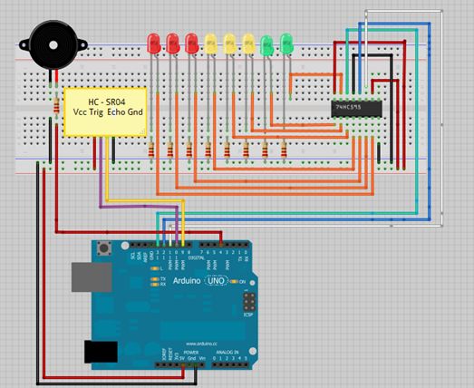
Arduino Ultrasonic Sensor with LEDs and buzzer

This is a tutorial for beginners who have recently started learning about electronics. The author has prior experience in programming with C and Python.
The schematic presented in this tutorial is designed for novice electronics enthusiasts who are transitioning from programming to hardware development. It emphasizes the fundamental concepts of electronics, including the use of basic components such as resistors, capacitors, diodes, and transistors.
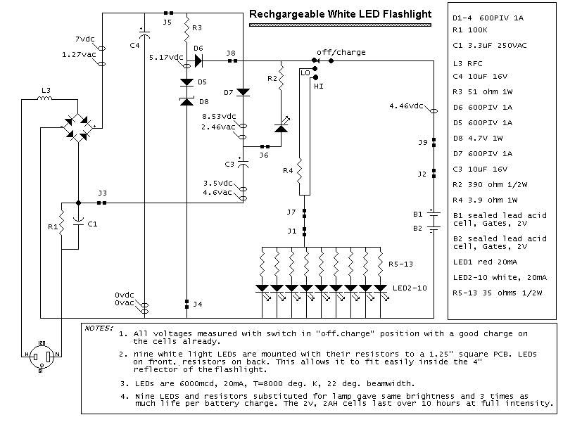
The circuit diagram typically illustrates a simple project, such as a basic LED circuit or a simple microcontroller-based project that allows users to apply their programming skills in a physical context.
For instance, a common introductory project might involve connecting an LED to a microcontroller, where the LED's brightness is controlled by varying the voltage through a pulse-width modulation (PWM) signal. The schematic would include a microcontroller pin connected to a resistor, which in turn is connected to the anode of the LED. The cathode of the LED would be connected to ground.
Additional components such as a power supply, typically a battery or a USB power source, would be represented in the schematic, ensuring that the circuit is powered appropriately. The importance of grounding and the correct orientation of components would also be highlighted, as these are critical for the successful operation of the circuit.
Overall, the tutorial serves as a practical introduction to electronics, bridging the gap between software programming and hardware design, and encouraging learners to experiment and build their own circuits.Hi guys this is my first tutorial, I`ve just started a few months ago learning electronics (previously I`ve just knew how to program in C and Python).. 🔗 External reference


