
Arduino IR Transmitter & Receiver w/ LEDs Flickering Issue (Whats wrong with this circuit?)
")
The circuit described involves an Arduino Uno interfacing with two IR transmitters and receivers, which are used for detecting interruptions in an IR beam. The LEDs are controlled to display specific patterns upon detection of a beam break. The flickering issue observed suggests a possible grounding or power supply interference problem, which can occur when multiple components share the same power source.
To address the flickering, it is advisable to isolate the power supply for the IR components from the Arduino. This can be achieved by using a dedicated external power supply for the IR transmitters and receivers. The voltage requirement for the IR components typically matches that of the Arduino, which is 5V. However, it is essential to verify the specifications of the IR transmitters and receivers to confirm their voltage requirements.
In determining the amperage output for the external power supply, the total current draw of the IR components should be calculated. This can be done by checking the datasheets for the specific IR transmitters and receivers to find their current consumption. Adding a margin of safety (typically 20-30%) to the total current requirement will ensure that the power supply can handle any additional load or inrush current when the components are activated.
Additionally, it is recommended to implement proper decoupling capacitors near the power pins of the IR components to filter out any noise that may contribute to the flickering. Using capacitors with values ranging from 0.1 µF to 10 µF in parallel can help stabilize the power supply.
In conclusion, isolating the IR components with a dedicated power supply, verifying their voltage and current specifications, and incorporating decoupling capacitors can significantly improve the performance of the circuit and eliminate the flickering issue experienced with the LEDs.An Arduino Uno connected to two IR transmitters and respective receivers. Basically, when one of the receivers detects a beam break, I have a strand of LEDs display a pattern. This all works in principle, but the problem is that when the IR transmitters and receivers are connected to the Arduino, the LEDs flicker with random colors.
Here`sa video of exactly what`s happening. At first, the IR transmitters and receivers are disconnected and everything is fine, then I connect the IR receivers and the flickering begins at around 8 seconds. . The flickering will continue even when I disconnect the IR receiver, albeit at a reduced rate. In the above diagram, the Arduino is powered via USB (I tried with a 12V power supply too), and the LED strand is powered from an external 12V power supply (I couldn`t find a diagram for an LED strand).
If it matters, I should mention that I`m using the IRremote library to control the IR transmitters ( ) and the strandtest example from the Adafruit WS2801 LED library ( ) to test everything right now. The strange thing is that I also have another strand of similar LEDs ( ) and they do not experience the flickering regardless of if the IR transmitters and receivers are connected or not.
So the only thing I can think of is to use an external power supply for the IR so as it avoid connecting them to the Arduino. Is that a valid solution If so, how do I got about determining what power supply I would need (in terms of voltage and amperage output)
🔗 External reference
Related Circuits

The trip point is set halfway between the supplies by R1 and R2; R3 provides over 200 mV of hysteresis to increase noise immunity. The maximum frequency of operation is about 300 kHz. If response to TTL levels is...
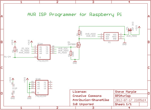
As a fully-featured Linux computer, many external programmers can be used with the Raspberry Pi to program the Atmel AVR range of microprocessors. It is also possible to utilize the general-purpose input/output lines (GPIOs) found on the Raspberry Pi...
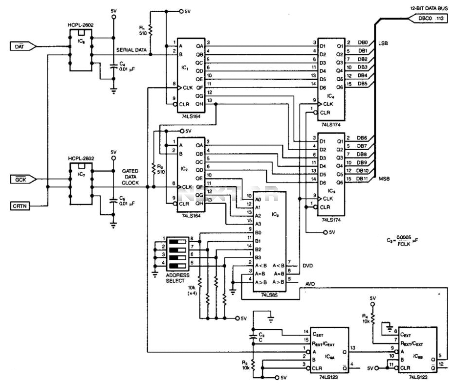
This 3-wire receiver verifies the initial four data bits of 16 received bits against a predetermined address. If the two match, the remaining 12 bits are stored in two 6-bit flip-flop registers. The design can utilize either CMOS or...
The circuit below demonstrates how to power one or two LEDs from a 120-volt AC line. It utilizes a capacitor to reduce the voltage and a small resistor to limit the inrush current. As the capacitor needs to allow...
Construct different power conversion circuits using an Arduino microcontroller. The Arduino microcontroller serves as a versatile platform for developing various power conversion circuits. These circuits can include DC-DC converters, AC-DC converters, and other forms of power management systems. The flexibility...
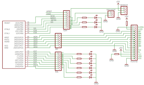
Required components include an Arduino Uno, an HD44780 Character LCD, a PING))) Ultrasonic Distance Sensor, a speaker cone from an old computer, a breadboard, wires, resistors, colored LEDs, and Arduino software. The provided schematic illustrates the parking sensor circuit....