
Nokia 2630 Camera Operation Failed Picture Help

The camera module in mobile devices like the Nokia 2630 and Nokia 2600c is integrated with the main circuit board through a series of connections. The failure of the camera operation can be attributed to various factors, including physical damage to the camera module, disconnections, or faults in the printed circuit board (PCB) traces.
In the event of a camera failure, the first step is to visually inspect the camera module and its connections to the PCB. Look for any signs of physical damage, such as cracks or loose connections. If the camera module appears intact, the next step involves using a multimeter to check for continuity along the circuit traces that connect the camera to the main processor. Broken traces can often be repaired using conductive ink or soldering techniques, depending on the extent of the damage.
Additionally, it is advisable to check for any short circuits that may cause the camera to malfunction. This can be conducted by measuring the resistance between the camera power supply pins and ground. If the resistance is significantly low, it may indicate a short circuit, necessitating further investigation to identify the faulty components.
The repair process may also involve replacing the camera module if it is found to be defective. This requires careful desoldering of the old module and soldering in a new one, ensuring that all connections are secure to restore functionality.
Photographic evidence of the damaged components, along with repair steps, can provide valuable reference material for technicians addressing similar issues in the future.Camera operation failed on Nokia 2630 has similar solution with the Nokia 2600c because they have the same board. The problem usually caused by the hardware damaged or broken line on the circuit. Here we have some pictures related to Nokia 2630 camera operation failed problem. 🔗 External reference
Related Circuits
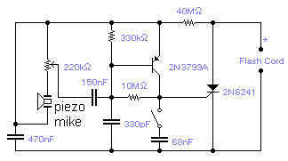
If you wish to take a picture of a fleeting event which generates a sound, you can do it with this sound activated trigger. It does not require any power supply: it feeds on the high voltage available on...
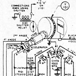
The CRV-59AAE measures 20 inches in length, 9 inches in width, and 10 inches in height, with a weight of 33 pounds. This device is over 60 years old and is in excellent condition, showcasing advanced miniaturized technology for...
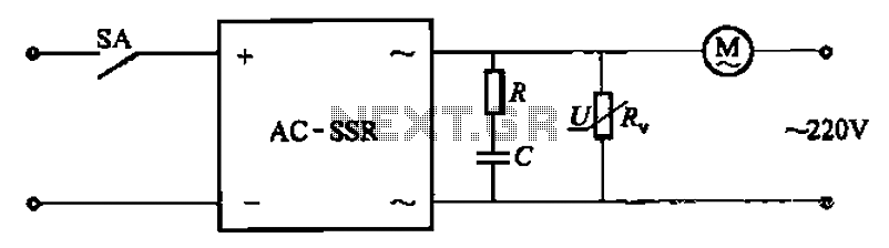
The circuit illustrated in Figure 3-13 is an RC surge absorption circuit that includes a resistor (R) and zinc oxide varistors (such as MY31, MYH12, MYH20 types, etc.), which serve as an overvoltage protection device. The resistance R is...
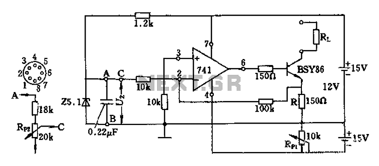
The Darlington transistor circuit BSY86 produces a large output current, with a maximum limit of 150 ohms. The output current is adjustable via resistor R and the RP1 potentiometer, maintaining constancy regardless of the load resistance Rl. The potentiometer...

This circuit serves as an alternative to the infrared beam break detector discussed in the June 2009 issue of Silicon Chip. It aims to provide a more efficient solution for detecting interruptions in an infrared beam. This alternative infrared beam...
In a servo system, the current drive connection is frequently utilized. The output current (IOUT) is proportional to the input channel number (y). Using the current drive mode can mitigate issues caused by the motor's large inductance, which induces...