
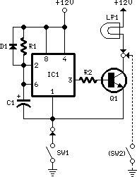
Current source circuit diagram of the operational amplifier and Darlington transistors
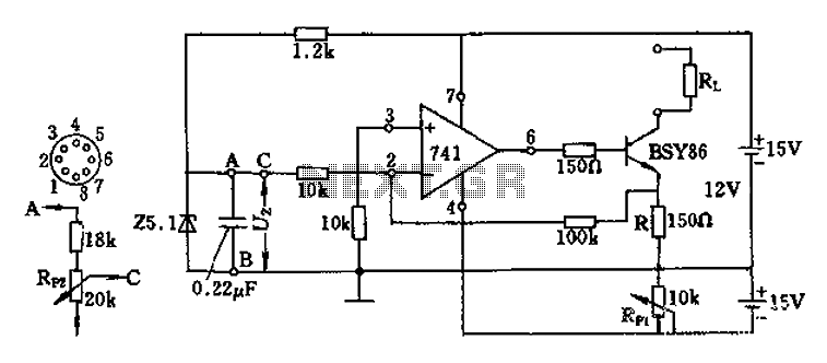
The described circuit employs a Darlington transistor configuration utilizing the BSY86 transistor to achieve high current gain. The output current is effectively managed through a combination of fixed and variable resistances, enabling fine control over the output characteristics. The adjustable resistor R, coupled with the RP1 potentiometer, provides a means to set the desired output current level, which is crucial in applications requiring precise current control.
The use of a 10k ohm potentiometer (RP1) is significant as it allows for a broad range of current adjustments, from a minimal 5µA to a maximum of 40mA. This flexibility is particularly useful in circuits where load conditions may change, ensuring that the output current remains stable and within specified limits. The incorporation of three inputs (A, B, C) further enhances the circuit's versatility, permitting alternative configurations depending on the application's requirements.
The adjustment of the emitter potential to ground through RP2 to -0.6V is a critical feature, as it establishes a reference point for the operation of the Darlington pair. This configuration can improve the linearity and response of the circuit, especially in applications involving signal amplification or current regulation. Furthermore, the ability to set the positive terminal potential to -12V enables the circuit to operate within a defined voltage range, optimizing performance while minimizing the risk of component stress.
Overall, this circuit design illustrates the effective use of a Darlington transistor in conjunction with adjustable resistive components to achieve a stable and controllable output current, suitable for various electronic applications.As a result of the Darlington transistor circuit BSY86 the output current is large. Output current 150 ohms maximum limit, the output current is adjusted by the resistor R by t he RP1 potentiometer, and maintained constant independent of the load resistance Rl. FIG potentiometer RP1 using 10k Europe, the current can be adjusted within the range of 5uA ~ 40mA. Op amp inputs A, B, C three partially available instead of confining potentiometer RP1, then the emitter potential BSY86 can be adjusted to the ground by RP2 -0.6V, the sliding contact of the potentiometer regulator positive terminal potential to -12V, then the resistance R and potentiometer RP1 can be canceled.
Related Circuits
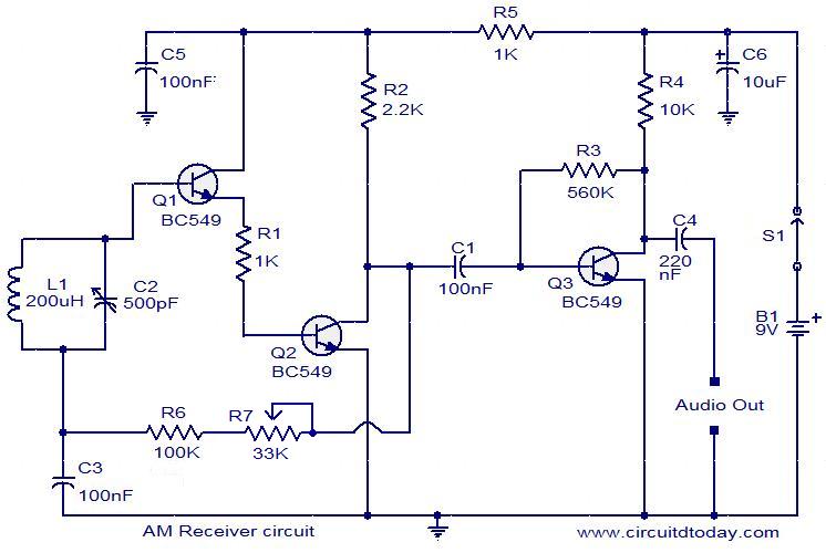
Circuit diagram of a modulator circuit in a transmitter and receiver of amplitude modulation. The modulator circuit in an amplitude modulation (AM) transmitter and receiver plays a crucial role in the process of encoding information onto a carrier wave. In...
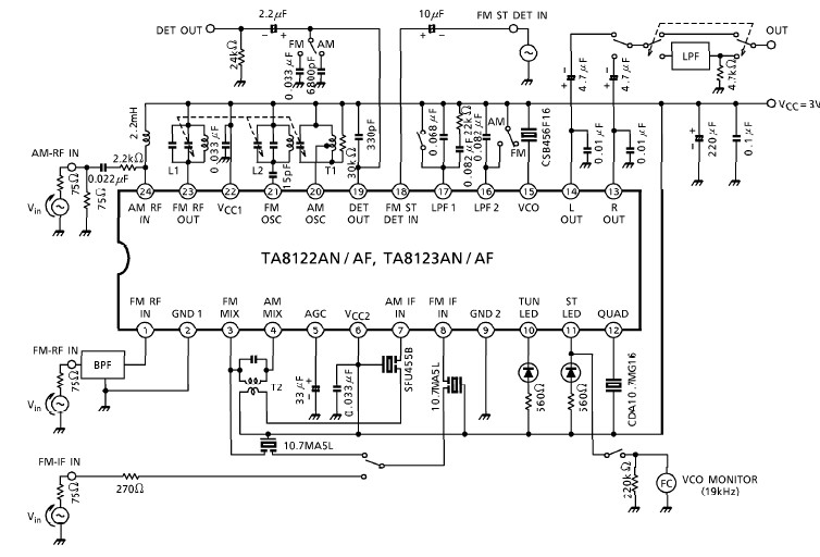
A simple low-power AM/FM radio receiver electronic project can be designed using the TA8122 integrated AM/FM receiver, manufactured by Toshiba Semiconductor. This radio receiver circuit can be utilized for portable radio applications or similar devices. The TA8122 radio receiver...
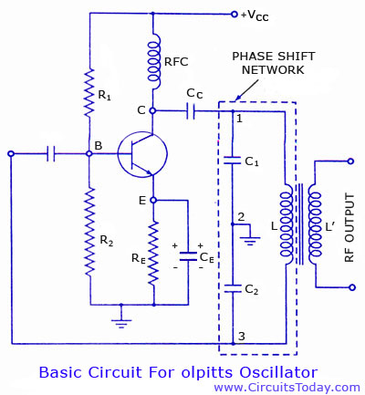
Colpitts oscillator circuit diagram and theory. Colpitts oscillator frequency equation. Colpitts oscillator using transistor. Colpitts oscillator using op-amp. The Colpitts oscillator is a type of electronic oscillator that generates sine waves and is widely used in various applications such as...

A motion detection alarm circuit utilizing a PIR sensor for motion detection. When movement is detected by the PIR sensor, it triggers a delay circuit, Q1, and other components. The motion detection alarm circuit is designed to provide an alert...
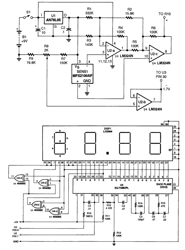
The LM324N is part of the LM324 family, which includes four independent, high-gain, internally frequency-compensated operational amplifiers. These amplifiers are designed to operate from a single power supply over a wide range of voltages. Operation from split power supplies...
When the door is opened, SW1 closes, powering the circuit and turning on the lamp. C1 begins to charge slowly through R1, and when the voltage at pins #2 and #6 of IC1 reaches 2/3 of the supply voltage,...
Warning: include(partials/cookie-banner.php): Failed to open stream: Permission denied in /var/www/html/nextgr/view-circuit.php on line 713
Warning: include(): Failed opening 'partials/cookie-banner.php' for inclusion (include_path='.:/usr/share/php') in /var/www/html/nextgr/view-circuit.php on line 713