
Solid state relay circuit controls the motor-way operation
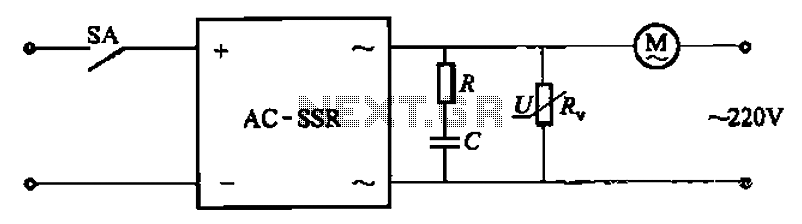
The RC surge absorption circuit is designed to protect sensitive electronic components from voltage spikes and transients that can occur in electrical systems. The resistor (R) and capacitor (C) form a low-pass filter that helps to dampen high-frequency voltage transients, while the varistor provides a clamping mechanism to divert excessive voltage away from the circuit.
The resistor R, rated at 5 watts, is critical in limiting the current that flows through the circuit during a surge event. The specified resistance values of 20 to 40 ohms are chosen to balance the trade-off between transient response time and energy dissipation. The capacitor C, with values ranging from 0.22 µF to 0.47 µF, provides the necessary capacitance to absorb energy from voltage spikes, thereby stabilizing the voltage level across the circuit.
The zinc oxide varistors, such as the MY31, MYH12, and MYH20 types, are selected based on their voltage ratings and energy absorption capabilities. These components are designed to exhibit non-linear resistance characteristics, allowing them to remain inert during normal operating conditions and to conduct heavily when the voltage exceeds their specified threshold. The optional flow capacity of 1 kA indicates the maximum current the varistor can handle without being damaged.
In applications where the circuit is exposed to 220V AC, the varistor is rated for a nominal voltage of 430 V to 480 V to ensure adequate protection. Conversely, for 380V AC applications, the varistor's voltage rating is increased to between 750 V and 820 V to accommodate higher transient voltages. This careful selection of components ensures reliable operation and longevity of the circuit in various electrical environments, providing essential overvoltage protection for critical electronic systems. Circuit shown in Figure 3-13. Figure, RC surge absorption circuit is, R, zinc oxide varistors (such as MY31 type, MYH12 type, MYH20 type, etc.), an overvoltage protection devic e. Resistance R- like to take 20 ~ 40C1 (big power 5w), capacitance C take 0. 22 ~ 0.47tF. Varistor R, optional flow capacity lkA, nominal voltage is 430 U1tnA 480V (AC 220V) or 750-820V (AC 380V).
Related Circuits
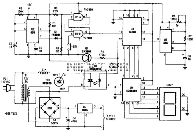
The electromagnetic ring launcher consists of four subcircuits: a clock circuit utilizing U5, a 555 oscillator/timer configured for astable operation; a countdown/display circuit incorporating U3, a 74190 synchronous up/down counter with BCD outputs set for countdown operation; U4, an...
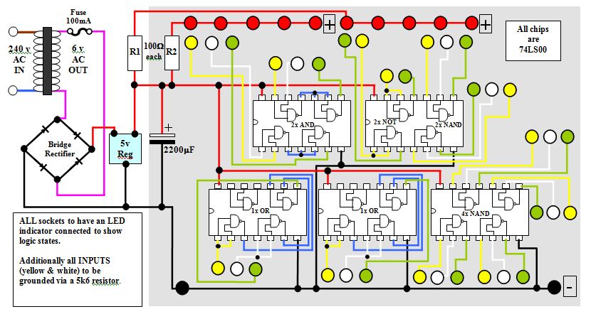
This circuit diagram for a logic tutor kit was created using MS Word graphics. While modern software is commonly utilized, there may be instances where traditional methods are necessary. Employ a sharp pencil and a ruler to ensure precision;...

This design outlines a power supply circuit capable of producing a 5V source voltage. The circuit is constructed using TTL integrated circuits (ICs) and features a simple design. In circuits utilizing TTL ICs, the supply voltage is critical, as...
The diagram illustrates a series connection of cell diode capacitors, each rated for an increasing voltage of 300 V. This configuration generates a high DC voltage supply of 40 kV, which can be utilized for various experimental applications. With...
This circuit describes a simple 6-bit random number pseudo-generator used to study binary counters and, in particular, shift registers. Some basic background information about binary counters and shift registers is provided. In reality, there are dozens of different shift...
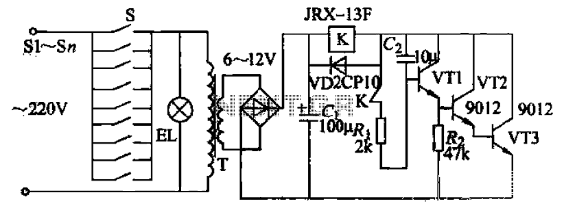
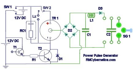
Pressing the button switch Sl-Sn activates the circuit, turning on the transformer T. The low-voltage alternating current from the secondary winding is directed to a bridge rectifier and a filter capacitor Ci, which produces a DC voltage. This voltage...