
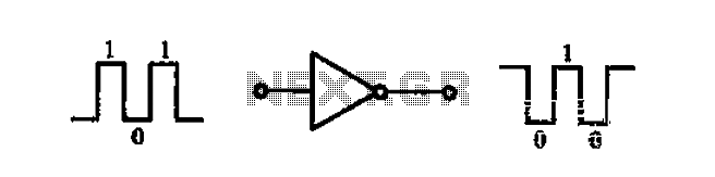
NOT circuit
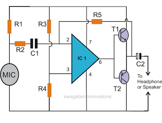
The common-emitter transistor amplifier is a widely used configuration in analog electronics, characterized by its ability to provide voltage gain and inverting characteristics. In this setup, the transistor operates in its active region, allowing for efficient signal amplification. The input signal is applied to the base terminal of the transistor, while the output is taken from the collector terminal. Due to the nature of the common-emitter configuration, a positive change in the input voltage results in a negative change in the output voltage, leading to the inverting behavior.
The circuit typically includes biasing resistors to establish the correct operating point for the transistor, ensuring linear operation and minimizing distortion. Capacitors may also be employed to couple the input and output signals while blocking DC components, allowing for AC signal amplification.
The NAND gate configuration mentioned refers to a specific logic gate that outputs a low signal only when all its inputs are high. This logic function can be implemented using combinations of transistors, diodes, or integrated circuits, depending on the desired application. The versatility of the common-emitter amplifier makes it suitable for various applications, including signal conditioning, audio amplification, and as a building block for more complex circuits.
DTL, TTL, and C-MOS technologies represent different approaches to digital logic design. DTL circuits utilize diodes to perform logic functions, making them simpler but slower compared to TTL circuits, which use transistors for faster switching speeds and better noise margins. C-MOS technology, on the other hand, is known for its low power consumption and high packing density, making it suitable for modern digital applications.
Overall, the common-emitter amplifier and associated logic circuits form the cornerstone of many electronic systems, enabling efficient signal processing and logic operations essential for various applications in telecommunications, computing, and control systems.A common-emitter transistor amplifier, the opposite phase output signal of the input signal, also known as an inverting amplifier. As this electrical path for amplifying the pu lse signal from the inverting amplifier is enabled, this circuit is a non-A circuit, that is, NAND gate logically. Is an integrated circuit made by a non-shown in FIG. gates, namely the inverter, the output signal of the opposite phase to the input, positive polarity pulse input impulse, the output is reverse polarity pulse gate logic signal processing system is the basic unit circuit, it has DTL type, TTL type and the C-MOS type three .DTL is diode Tranaistor logic (diode-transistor logic) is the abbreviation .TTL transistor transistor logic (transistor transistor logic) for short.
the difference between these two is dTL logic circuit uses a diode for the input circuit. TTL uses transistors as the input path .C-MOS is an abbreviation for Complementary MetaJ Oxide Semiconductor, this circuit is mainly used C-MOS FET logic circuit of tubes.
Related Circuits
The automatic sprinkler controller circuit consists of a +12 V power supply circuit, a light control circuit, and an irrigation control circuit, as illustrated in the accompanying figure. The +12 V power supply circuit includes a knife switch (Q),...
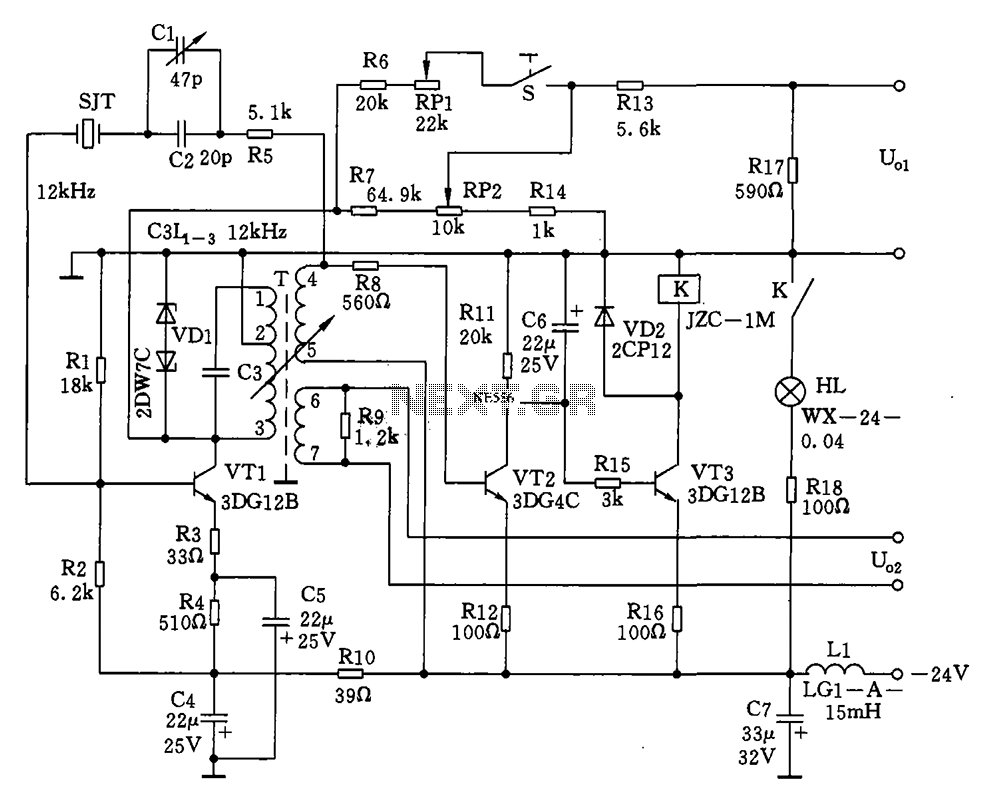
The circuit features a 12kHz intermediate frequency (IF) oscillator utilizing a quartz crystal for precision frequency generation. It includes components for output level adjustment, a level-up circuit, and an alarm circuit. The design employs a unique single-tuned variable feedback...
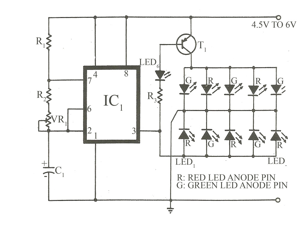
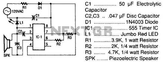
This circuit is similar to various published flasher circuits that utilize the IC 555 as a free-running multivibrator. The primary distinction is in the method of flashing bi-color LEDs. When the output at pin 3 of the IC 555...
The circuit presented is experimental and should provide some fun to build and play about with. It has been built and tested and works very well indeed. Please note that it is a low current Class-A opamp and is...
This document discusses the creation of an electronic spy bug circuit using two methods: one involving a wired connection from the transmitter to the receiver, and the other being a completely wireless setup capable of eavesdropping on conversations up...
The tester comprises a rectifier circuit and a multivibrator circuit. The alternating current (AC) voltage is half-wave rectified by diode D1 and stored in capacitor C1. Resistor R1 is employed to limit the current through D1 to a safe...
Warning: include(partials/cookie-banner.php): Failed to open stream: Permission denied in /var/www/html/nextgr/view-circuit.php on line 713
Warning: include(): Failed opening 'partials/cookie-banner.php' for inclusion (include_path='.:/usr/share/php') in /var/www/html/nextgr/view-circuit.php on line 713